Join us on an alphabetical journey through the research themes and key concepts behind our work!
A is for Acoustics
Sound is all around us: it accompanies everything we do. Human beings are both sources and the receivers of sounds. Acoustics is the branch of science and engineering concerned with all aspects of sound, including its generation and transmission, its control and use, and its effects on people and the environment.
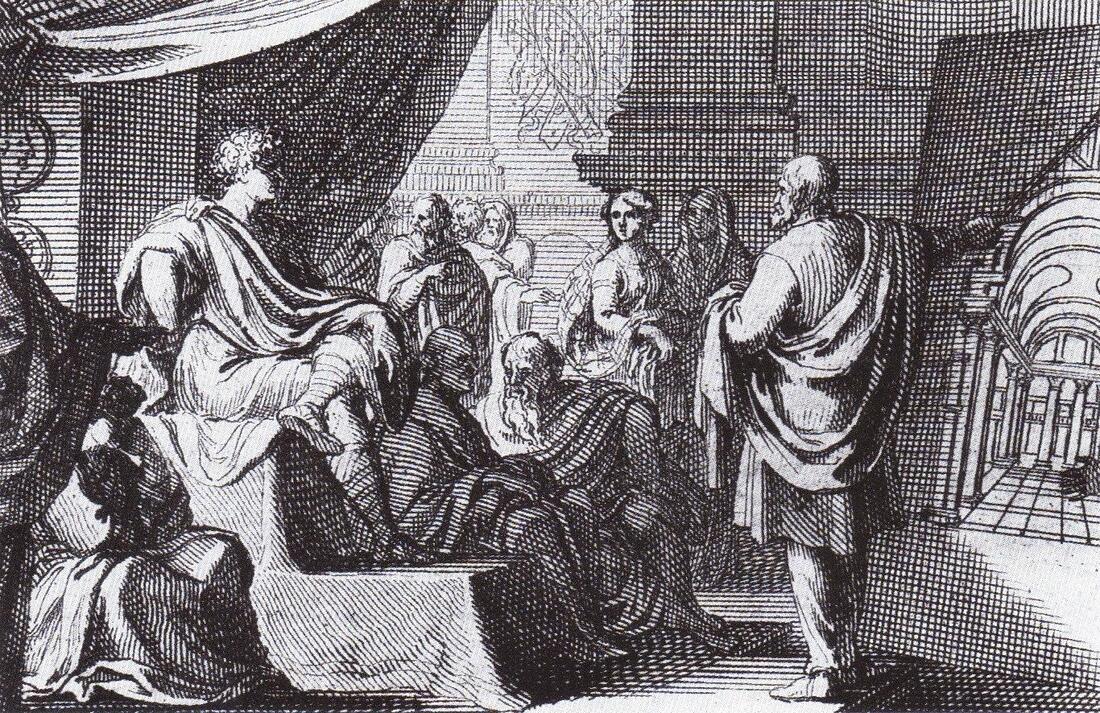 Vitruvius presenting De Architectura to Augustus. From Vitruvius on Architecture (1684) by Thomas Gordon Smith. Image credit: Sebastian Le Clerc, public domain, via Wikimedia Commons
The scientific study of sound dates at least as far back as the 6th century BCE, with experiments by Greek philosopher and mathematician Pythagoras into harmonics and vibrating strings [1]. Several centuries later, the Roman engineer and architect Vitruvius (d. 15 BCE) is credited with the first formal treatment of architectural acoustics in his multi-volume work De Architectura, in which he discusses sound propagation in theatres [2].
The use of the term “acoustics” to define a branch of science came much later. Although the word had been used in the context of sound previously [3], the definition is usually attributed to physicist and mathematician Joseph Sauveur, who in 1701 proposed a new field of study called acoustique. He described his new discipline as “a science superior to music”, because it encompassed all sound, not simply music and harmonics [4].
The use of the term “acoustics” to define a branch of science came much later. Although the word had been used in the context of sound previously [3], the definition is usually attributed to physicist and mathematician Joseph Sauveur, who in 1701 proposed a new field of study called acoustique. He described his new discipline as “a science superior to music”, because it encompassed all sound, not simply music and harmonics [4].
When we think about acoustics the first thing that springs to mind might be architectural acoustics, and the optimisation of indoor sound. However, modern acoustics is a multidisciplinary field, encompassing physics, material science, engineering, psychology, physiology, music, architecture, neuroscience, environmental science and mathematics. Some of the many other branches of acoustics include:
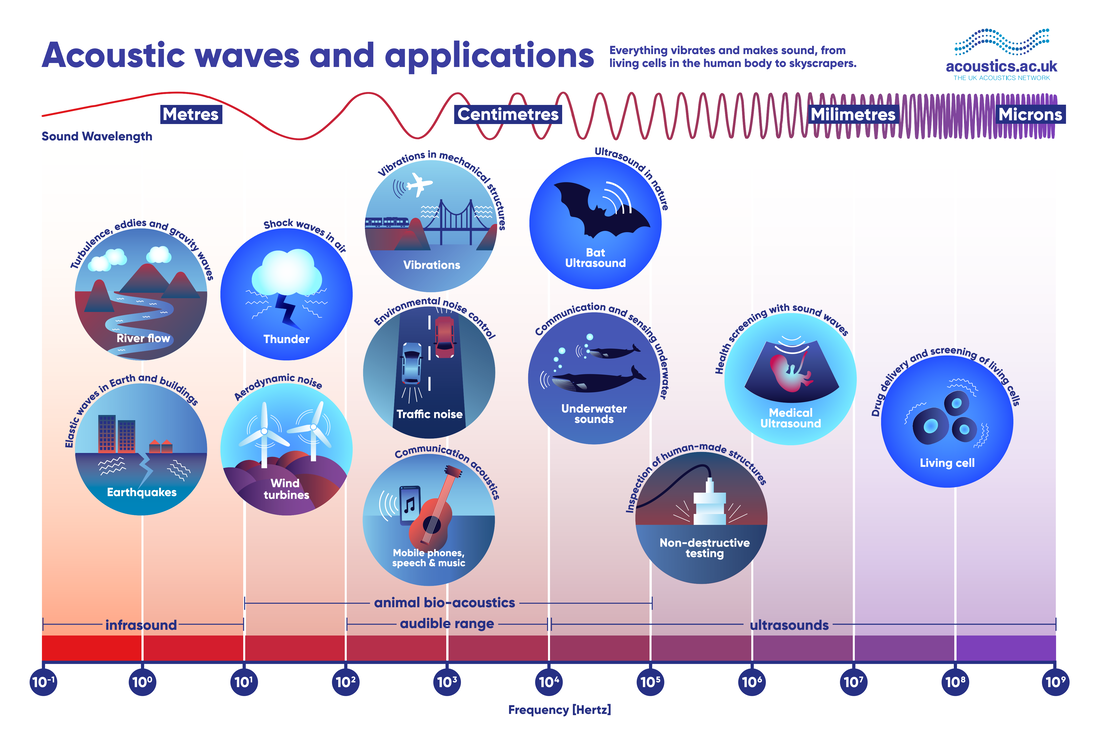 Image created by UK Acoustics Network members, reproduced with permission.
Physical acoustics: Physical acoustics overlaps with other fields of acoustics such as engineering and medical imaging. It also encompasses sound beyond the human audible range. Frequencies below the audible are called infrasound. Many natural phenomena such as earthquakes and thunder generate infrasound. Higher frequency sound is ultrasound, whose uses in medical imaging are well known. There are many other interesting physical acoustic phenomena, such as the photoacoustic effect: where sound is generated by the interaction of light with matter.
Musical acoustics: This is a broad field encompassing the design of musical instruments, building acoustics, the human perception of sound and music, and music recording and reproduction.
Psychoacoustics and physiological acoustics: These include the study of people's perception of sound and its physical and pshychological impact on us, and the physiology of hearing and hearing-loss.
Underwater acoustics and oceanography: The study of underwater acoustics and sonar has military and commercial applications, while in marine biology, acoustics can lead to a better understanding of animal communication, and the effect of human-generated noise on marine animals.
Environmental noise control: We know that exposure to loud noise can cause hearing loss, but this is not the only adverse effect. Noise can reduce our quality of life, and even our life expectancy, causing an estimated 12,000 premature deaths in Europe each year [7]. For this reason, noise reduction and control is an extremely active branch of acoustics.
|
|
Researchers in the Mathematics of Waves and Materials group apply mathematical modelling to acoustics. Research themes include the design of acoustic metamaterials and phononic crystals: materials whose properties are determined by their structures, rather than their chemical composition. Acoustic metamaterials have structural elements that are smaller than the wavelengths of the sounds they are designed to interact with. This leads to properties that are not found in conventional materials. Other areas of acoustical research within the group include aero- and hydroacoustics: the study of the noise generated by fluid flows both on their own (jet noise) and when interacting with solid boundaries (trailing edge noise) in air and water, and the interaction of soundwaves with materials, including nanofibrous materials.
|

2020-2021 is the International Year of Sound, a global initiative to highlight the importance of sound and acoustics in society. You can find learning resources and events from acoustics organisations around the world on the Year of Sound website.
[1] Zhmud, L. (2012) "8: Harmonics and Acoustics in Pythagoras and the Early Pythagoreans", Oxford Scholarship Online
[2] Maconie, R. (2005) "Musical Acoustics in the age of Vitruvius", Musical Times; London, 146: 75-82.
[3] Dostrovsky, S. (2008) "Sauveur, Joseph", in Complete Dictionary of Scientific Biography vol. 12, New York, NY: Charles Scribner's Sons, 127-129.
[4] Fix, A. (2015) "A Science Superior to Music: Joseph Sauveur and the Estrangement between Music and Acoustics", Phys. Perspect., 17: 173–197.
[5] Rossing, T. D (2014) "A Brief History of Acoustics" in Springer Handbook of Acoustics. New York, NY: Springer, 9-24
[6] Rossing T.D. (2014) "Introduction to Acoustics" in Springer Handbook of Acoustics. New York, NY: Springer, 1-6
[7] European Environment Agency, Environmental noise in Europe — 2020, EEA Report No 22/2019
B is for Boundary Conditions
Just as in high school mathematics or physics, where one imposes conditions on the solution to an ordinary differential equation (such as a simple harmonic oscillator), in continuum mechanics boundary conditions are imposed on the solutions to partial differential equations which represent mathematically the laws governing the generic behaviour of particular materials.
|
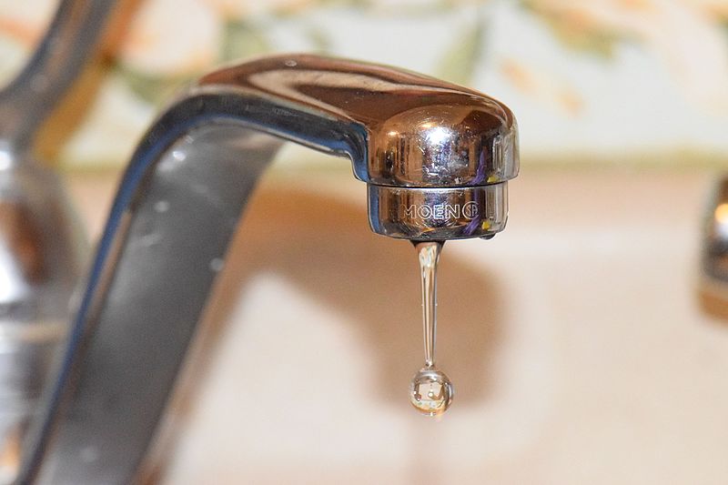
A familiar example is the dripping of a tap. As water slowly accumulates at the outlet of the tap, its surface forms a smooth near-spherical shape as a consequence of surface tension acting to minimize the exposed surface area. Eventually, it becomes energetically expedient for a drop to detach and fall away, and the process repeats. The partial differential equations in this context are the Navier-Stokes equations, and the boundary conditions are the surface tension at the interface between water and air, the pressure gradient or the flow rate within the tap, and also the contact conditions at the meeting point between water, air, and the tap itself. In general, the flow of water, or any Newtonian fluid, is a function only of the Reynolds number and the boundary conditions.
|
Credit: PumpkinSky, CC BY-SA 4.0: https://creativecommons.org/licenses/by-sa/4.0 via Wikimedia Commons
|

Credit: Spigget, CC BY-SA 3.0: https://creativecommons.org/licenses/by-sa/3.0, via Wikimedia Commons
|
The refraction of a light ray as it passes from one medium into another can also be understood in terms of boundary conditions applied at the interface between the two media. Solving the Euler-Lagrange equation, one can show that \(\frac{sin \theta}{c}\) must be the same on either side of the boundary, where θ is the angle of incidence on one side and the angle of refraction on the other side, and c is the local speed of light in each medium. This result is known as Snell's Law, although it was described by Ibn Sahl almost 600 years before Snell was born [1].
|
The extent to which the full detail of the boundaries are incorporated within a mathematical model can depend on whether there is a practical need for a quantitative result in a particular case, for example, the stress on a rocket's nose cone, or the circulation of air in a hospital. If the intention of the modelling is mainly to understand the underlying phenomena in a more qualitative sense, then an idealized and representative form of the problem is often developed, typically involving simplifications in the form of assumptions about spatial symmetry, infinite extent, or smoothness of walls etc. Such simplifications are usually intended to allow a certain amount of progress with a purely analytical approach, or for testing of a computational approach at a proof of concept stage. Solving the fundamental equations in full generality may be impossible, but with restrictions on the possible solutions, e.g. an assumption of spherical symmetry, or taking an asymptotic limit in terms of a small parameter, the problem may become tractable. In effect, the simplifications can be interpreted as modifying the boundary conditions. Then the relevance of the idealized solution in the context of the full unsimplified problem will depend on whether the boundary conditions are amenable to the sort of simplifications discussed.
When assessing the robustness and accuracy of a new computational algorithm, certain well-studied and sometimes challenging combinations of boundary conditions are used, known as benchmark problems. These are problems for which the correct solutions are known, and the idea is to highlight any limitations of the algorithm, or any mistakes made in its implementation. For example, the lid-driven cavity is a standard benchmark problem in CFD (computational fluid dynamics) for the validation of numerical methods [2].
When assessing the robustness and accuracy of a new computational algorithm, certain well-studied and sometimes challenging combinations of boundary conditions are used, known as benchmark problems. These are problems for which the correct solutions are known, and the idea is to highlight any limitations of the algorithm, or any mistakes made in its implementation. For example, the lid-driven cavity is a standard benchmark problem in CFD (computational fluid dynamics) for the validation of numerical methods [2].
|
N. F. Morrison
|
[1] Rashed, R. (1990) "A Pioneer in Anaclastics: Ibn Sahl on Burning Mirrors and Lenses", Isis, 81(3): 464-491
[2] Hinch, E. J. (2020) "1: The Driven Cavity" in Think Before You Compute. Cambridge: Cambridge University Press, 3-8
[2] Hinch, E. J. (2020) "1: The Driven Cavity" in Think Before You Compute. Cambridge: Cambridge University Press, 3-8
C is for Composite Materials
Composite materials can be defined as materials manufactured by the combination of two or more phases, to perform tasks that neither of the constituent materials can achieve alone. One phase is continuous and is called matrix while the other phase which is discontinuous is known as reinforcement or filler [1] (Figure 1). The matrix material binds the reinforcement and gives composite its net shape. The interfacial region between reinforcement and matrix in composites facilitate the transfer of forces between the relatively weak matrix and stronger reinforcement. A strong interfacial bond is necessary to enhance the mechanical properties of the composites.
|
Composite materials offer superior properties than their base materials. Humans have been making composites since ancient times. Adobe brick is an early example of a composite, made of straw and mud. Wood is also an example of composite material, made from long cellulose fibres held together by lignin. In recent times, the use of composite materials has increased in the aerospace, automotive, marine, defence, wind/energy and construction industries due to their light weight nature, high specific stiffness and strength, corrosion resistance, buoyancy, damage tolerance, impact resistance, and damping and sound absorbing properties.
|
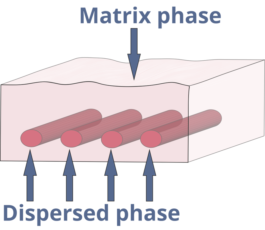
Fig. 1 Schematic of a composite material, showing the matrix and dispersed, or filler phases.
|
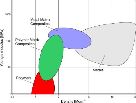
Fig. 2 Young’s modulus and density of metals, polymers and composites, from [2]. Reproduced under a creative commons CC BY-NC-ND 3.0 license: https://creativecommons.org/licenses/by-nc-nd/3.0/
|
The Young’s modulus and density relation of metals, polymers and composites is presented in Figure 2, which shows that composite materials can offer better specific stiffness (E / ρ) than metals.
The properties of composite materials can be tailored by selecting appropriate combinations of matrix and filler/reinforcement. The volume fraction of reinforcements also plays an important role in determining the performance of composites. Based on the type of matrix material, composites are generally classified as polymer matrix composites (PMCs), metal matrix composites (MMCs), ceramic matrix composites (CMCs) and carbon matrix composites (CAMCs) |
PMCs are most widely used type of composites. They are further divided into different categories, namely: thermosets, thermoplastics and elastomeric composites. Thermoset matrices are used in high performance composite materials. They become rigid after curing and can be used at elevated temperatures without losing structural rigidity. Thermoplastics, unlike thermosets can be melted on heating. Examples of thermosetting polymer matrices include polyester, vinyl ester, epoxy, phenolic, cyanate ester, polyurethane, polyamide and bismaleimide. Polyethylene, polypropylene, polyamide, PEEK, thermoplastic polyamide, thermoplastic polyurethane, polycarbonate, PLA, polysulfone, polyphenylene sulphide are all examples of thermoplastic polymer matrices. Elastomers achieve their cross linking as a result of the vulcanization process. Rubber is a well-known elastomeric material. Metal, ceramic and carbon matrices are used for highly specialised objectives. For example, ceramics are used for high temperature applications, and carbon is used for applications which are expected to undergo friction and wear.
A variety of filler/reinforcement materials are available. Fibre reinforced composites are popular for high strength/weight and high modulus/weight ratios. Different fibres like glass, carbon, boron, ceramic, metal and natural fibres like flax, sisal and hemp are used as reinforcements in many applications. Composites made from carbon fibres are popular in aerospace, owing to their strength and weight reduction characteristics. Components made from carbon fibre reinforced composites can be five time stronger than 1020 grade steel, while utilising only 20% of the weight of steel. In aerospace applications, high strength and weight reduction are highly desirable properties, for structural integrity and fuel economy. The use of composite materials in Boeing 787 aircraft is depicted in Figure 3.
A variety of filler/reinforcement materials are available. Fibre reinforced composites are popular for high strength/weight and high modulus/weight ratios. Different fibres like glass, carbon, boron, ceramic, metal and natural fibres like flax, sisal and hemp are used as reinforcements in many applications. Composites made from carbon fibres are popular in aerospace, owing to their strength and weight reduction characteristics. Components made from carbon fibre reinforced composites can be five time stronger than 1020 grade steel, while utilising only 20% of the weight of steel. In aerospace applications, high strength and weight reduction are highly desirable properties, for structural integrity and fuel economy. The use of composite materials in Boeing 787 aircraft is depicted in Figure 3.
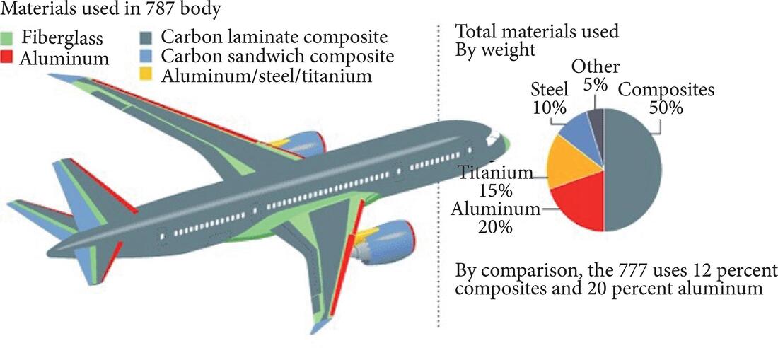
Fig. 3 Usage of composite materials in Boeing 787, from reference [3], reproduced under a creative commons cc by 4.0 license: https://creativecommons.org/licenses/by/4.0/deed.en
Composites manufactured by the combination of hollow microballoons (of glass, ceramic and plastic) and polymer matrix, generally known as syntactic foams, are popular for their acoustic, buoyancy, low moisture absorption and weight saving characteristics, and find their applications in marine and aerospace structures.
Numerous methods are available to manufacture composites, for example resin transfer moulding (RTM), vacuum infusion (VI), vacuum assisted resin transfer moulding, compression moulding and 3D printing. The selection of manufacturing method will mainly depend on the materials, part design and application.
Z. Yousaf
[1] Issac, M., Daniel O. I. (2006) Engineering mechanics of composite materials, New York: Oxford University Press
[2] Kickelbick, G. (2014) Hybrid Materials – Past, Present and Future, Hybrid Mater, 1: 39-51. DOI: 10.2478/hyma-2014-0001
[3] Alemour, B., Badran, O. & Hassan, M. R. (2019), A Review of Using Conductive Composite Materials in Solving Lightning Strike and Ice Accumulation Problems in Aviation, Journal of Aerospace Technology and Management, 11: e1919.
D is for Diffraction
|
The term diffraction was coined in 1666 by Francesco Maria Grimaldi, after experimenting with light. He shone a light through a small hole in an opaque plate, and found that the light cast into the room covered an area larger than the hole it travelled through. This suggests that the light is not travelling in straight lines through the hole but is bent around the corners of the hole [1]. This can be seen in Figure 1, where the wave becomes curved as it passes through the slit, covering an area larger than the slit on the other side. The theory of diffraction can be extended beyond light passing by opaque surfaces, to any system of waves travelling past or around an object. Whether those waves be acoustic, elastic, electromagnetic or even oceanic waves - all can be diffracted.
|

Fig. 1. Diffraction through a slit. Credit: Inductiveload, Public domain, via Wikimedia Commons
|
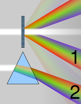
Fig 2: Diffraction (1) and Refraction (2). Credit: Cmglee, CC BY-SA 3.0
|
A practical use of diffraction can be seen in the use of diffraction gratings. Diffraction gratings are periodic structures, which split light into its component wavelengths. This phenomenon occurs as the diffraction of a wave is dependent its wavelength, hence the multiple wavelengths of visible light are diffracted at different rates as they pass through the grating. Therefore, after the light passes through the grating we can see each colour component. Diffraction gratings can be used as a tool in spectrometers - used to analyse the light emitted by a material. They can also be seen in items such as CDs, where the data engraved into the CD causes light to be diffracted when shined upon it.
The theory of diffraction is not to be confused with refraction, which is the warping of waves due to passing through a material, rather than around a material. In Figure 2, we can see light being diffracted by a grating in the top image, and light being refracted by a glass prism below.
|
|
Diffraction can not only be seen in light waves, but in any travelling wave front. For example, in the animation on the right, we see the diffracted wave field of a plane wave travelling from the right hand side, by what we call a half-plane. The half-plane is an infinitely thin line, starting at \(x = 0\), and extending to negative infinity, \(-\infty\), to the left. On the right hand side we see a field which is reflected by the edge of the half-plane and looks like a cylindrical plane wave. However, on the left hand side, where the wave is travelling past the half-plane, we see that the wave front is no longer constant due to the bending around the plane.
|
|
Scientists have gained a lot of insight about the world around us by the theory of diffraction. Most interesting is the occurrence of diffraction in the quantum world. Quantum physics is the study of matter and energy at the most fundamental level. In general, quantum theory considers the smallest of particles, and since these particles are the building blocks of the solid world around us, you would maybe expect that they behave like solid objects. However, US physicists Clinton Davisson and Lester Germer performed an experiment where electrons were fired in a stream through a small slit and their position recorded on the other side [2]. If each particle were to behave like a discrete solid object, we would expect to see the shape of the slit replicated in the image on the other side. However, it was found that the particles are actually diffracted and show wave-like behaviour, creating an image greater than the size of the slit when recorded.
T. White
[1] Cajori, F. (1899) A history of physics in its elementary branches: including the evolution of physical laboratories, New York: Macmillan
[2] Ball, P. (2018) Two slits and one hell of a quantum conundrum, Nature, 560 (7717):165-166
Animation credit: M. Nethercote
[2] Ball, P. (2018) Two slits and one hell of a quantum conundrum, Nature, 560 (7717):165-166
Animation credit: M. Nethercote
E is for elasticity
|
Elasticity is the property of a material that enables it to recover its original form when it is stretched, compressed, or otherwise deformed. All materials are elastic; stiff materials like steel and even diamond exhibit elasticity to a certain extent but the property is more easily visualised in materials that are highly deformable, e.g. rubber (elastic) bands or soft foams, see Fig. 1.
We usually describe the elasticity of a material by its relationship between force and extension, or equivalently by its stress-strain relationship, where stress is the force applied per unit area, and strain is the degree of deformation. With reference to Fig. 2, many materials exhibit a linear force- extension, or stress-strain relationship, and this type of
|
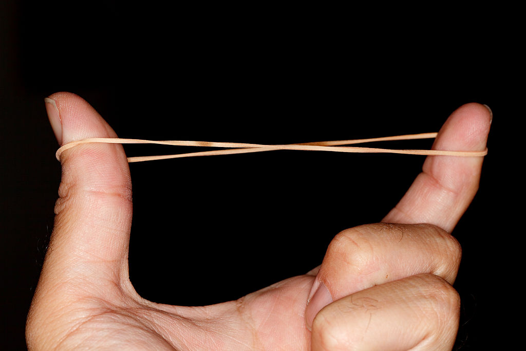
Fig. 1. Credit: Sander van der Wel, CC BY-SA 2.0, https://creativecommons.org/licenses/by-sa/2.0, via Wikimedia Commons
|
elasticity is therefore known as linear elasticity. The origin of this was the work of Robert Hooke, who in 1660 discovered that the extension of a spring is proportional to the weight that is applied to the spring, see Fig. 3. Obviously, if we keep adding weight to the spring, at some point it is no longer able to sustain this loading and it will break. Just prior to this in fact, the material from which the spring is made will have undergone so-called plastic deformation. This is where the atoms comprising the material are forced apart permanently. This is illustrated in Fig. 2, where we indicate that all of this behaviour is beyond the elastic limit. If weights (or more generally, forces) remain within the regime of elasticity then when the weight is removed, the spring will return back to its original rest state.
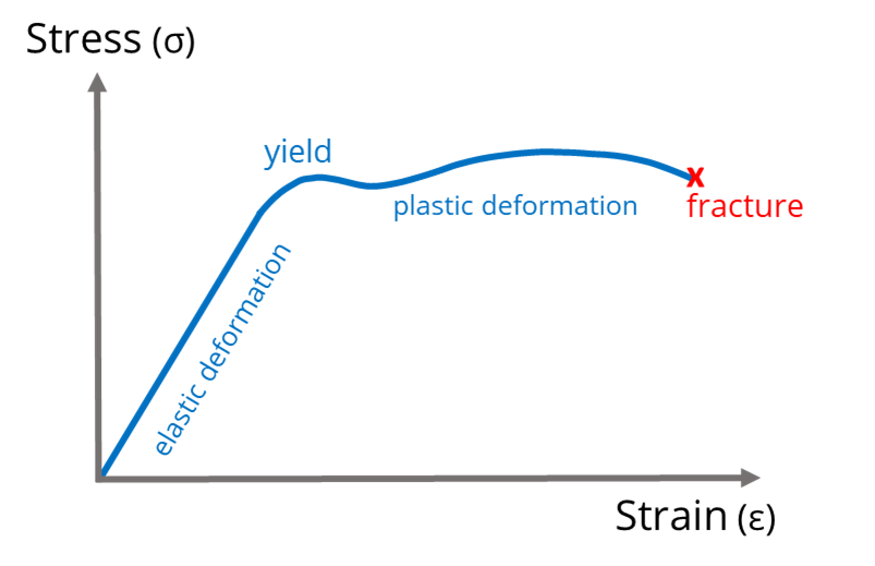
Fig. 2. Stress-strain curve illustrating the elastic and plastic deformation and eventual fracture of a material.
|
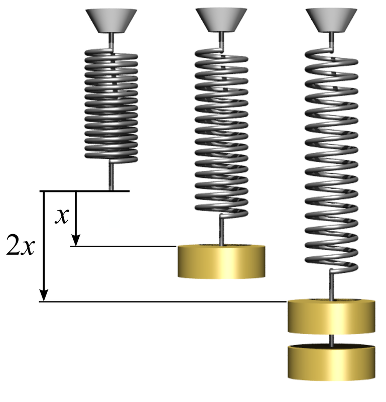
Fig. 3. Hooke's Law. Credit: Svjo, CC BY-SA 3.0, https://creativecommons.org/licenses/by-sa/3.0 via Wikimedia Commons
|
In reality, perfect elasticity is not possible, and according to the second law of thermodynamics there will always be some form of loss in the system, e.g. via friction or heat. This amount of loss is measured by the area between the load and unload curves in the stress-strain relationship, see Fig. 4. However we can get very close to perfect elasticity in many systems (the spring is a very good example) and especially so if we deform the material very slowly.
|
The elasticity of a material can be defined by its so-called elastic modulus, which is frequently termed Young’s modulus, named after Thomas Young and his work in the 19th century. When put under tension, as we have already discussed, many materials can be defined by their stress-strain relationship, i.e. \(\sigma = E e\) here \(\sigma\) is the stress applied in tension, \(e\) is the extensional strain and \(E\) here is Young’s modulus. The larger \(E\) is, the more stiff the material, given that it takes more stress (or force) to yield a fixed strain. In this context then, stretching your ear is much more straightforward (try it, but don’t pull too hard!) than stretching a piece of concrete or diamond.
|

Fig. 4. Stress strain curves for perfectly elastic and real materials. The red shaded area represents energy loss in the system.
|
To put some numbers on this, the Young’s modulus of a soft material such as rubber is around 6 times smaller than that of diamond. Therefore if a given stress of say 1MPa is applied to a piece of rubber it would yield a strain of around 10%, whereas the strain in diamond would be only 0.0001%. This is precisely why then you can visualise elasticity in soft tissue and rubber but not in very stiff materials such as diamond. This is also why there is a general perception that stiff materials such as wood, steel and diamond are not elastic. In reality they are, it is just that one cannot see this with the naked eye.
Now, not all materials are linear elastic for their entire regime of elastic deformation, although they usually are in some limit, close to the origin of the stress-strain curve. Indeed, we just described the example of soft tissue and this is very nonlinear, by which we mean that the material is not Hookean and does not exhibit proportionality between stress and strain. Its behaviour is defined by a more complex relationship between stress and strain. The study of such materials is known as nonlinear elasticity. Understanding this nonlinear relationship is extremely important and assuming that an elastic response is linear when it is not can be very dangerous. Consider for example the case of a bungee cord, responsible for the safe but exciting launch of someone over the side of a bridge into a ravine below. Typically bungee cords are nonlinear
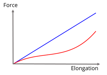
Fig. 5. Graph of force vs extension for a linear elastic (blue curve), and non-linear elastic (red curve) material.
|
elastic, exhibiting the kind of stress strain relationship depicted in the red curve of Fig. 5. As we can see, for a given force (weight) the bungee cord would extend much further than it would if it were linear elastic (the blue curve in Fig. 5), with its Young’s modulus assumed to be that which is measured in the small strain regime. If we are relying on the cord to stop us at the correct distance (depending on what is below us!) then we should ensure that we have a good understanding of the elasticity of the cord! More generally, nonlinear elasticity is critical for the design of many soft materials, e.g. polymers, isolation mounts, maxillofacial prosthetics, artificial tendons amongst others.
|
Understanding a material’s elastic response is fundamental to humankind. It plays a critical role in almost everything that we do from taking a walk (made possible by the elasticity of our tendons and ligaments), to driving a car (the elasticity of tyres is crucial, as well as the suspension of the car), to understanding how earthquakes (elastic waves that propagate through the earth) could potentially cause damage to entire cities. In the context of designing materials therefore, understanding and subsequently modifying the design of the elasticity of the material is something that is absolutely critical. Mathematical models are important for this purpose, particularly in order that we can reduce the amount of experimental testing and therefore reduce the impact on the environment. Modelling allows us to consider the impact of a huge parameter space of properties and how they impact on the overall elasticity of complex materials. Our research group has carried out a variety of work over the last decade in the areas of composite materials and elastic metamaterials.
W. J. Parnell
F is for Frequency
Frequency is a simple property, but one which underpins a vast amount both of science and of our sensory perception of the world. The frequency of a wave is the number of whole waves that pass a fixed point in one second, and is the inverse of the wave’s time period. The SI unit for frequency takes its name from German physicist Heinrich Hertz, who proved experimentally James Clerk Maxwell’s theory of the electromagnetic field [1]. One hertz (Hz) is equivalent to one cycle, or oscillation, per second.
Wave velocity, \(v\), wavelength, \(\lambda\), and frequency \(f\) are connected by the relationship \(v = \lambda f\), from which it follows that for waves travelling at a fixed velocity, frequency and wavelength are inversely proportional.
Wave velocity, \(v\), wavelength, \(\lambda\), and frequency \(f\) are connected by the relationship \(v = \lambda f\), from which it follows that for waves travelling at a fixed velocity, frequency and wavelength are inversely proportional.
|
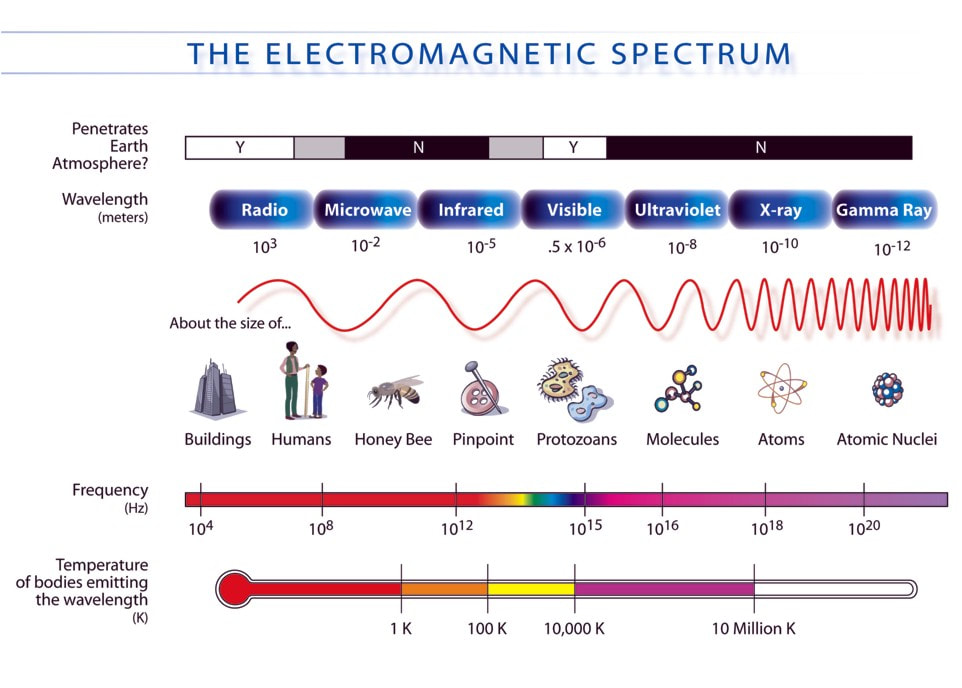
Frequency and electromagnetic waves
The illustration on the right depicts the electromagnetic (EM) spectrum, from radio waves, with frequencies below about 300 GHz and wavelengths greater than 1mm; to high frequency gamma rays, with frequencies above \(10^{19}\) Hz, and wavelengths on the scale of atomic nuclei. The range of frequencies visible to humans represents only a very narrow slice of the EM spectrum, between \(4 \times10^{14}\) Hz (red) and \(8 \times 10^{14}\) Hz (violet). Other animals are able to see different frequencies, including arctic reindeer, whose vision extends into the ultraviolet, which may enable them to distinguish food such as UV-absorbing lichen in the arctic winter [2]. |
Credit: NASA, Public domain via Wikimedia Commons
|
Credit: Dragons Flight at English Wikipedia., CC BY-SA 3.0 http://creativecommons.org/licenses/by-sa/3.0/, via Wikimedia Commons
|
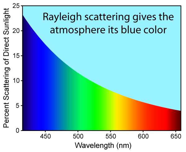
Wave behaviours such as refraction, diffraction and scattering are frequency dependent. The sky gets its blue colour from the frequency dependence of Rayleigh scattering (left), where light is scattered by particles much smaller than the wavelengths of the light, such as molecules in air. The scattering intensity (the amount of light scattered at a given angle) is proportional to the fourth power of the frequency of the light, so blue light is more scattered than red.
Frequency in sound waves
While the range of visible light spans less than one order of magnitude, humans can hear sounds ranging between about 20 Hz and 20 KHz in frequency. This corresponds to wavelengths in air of between 17 mm and 17 m. Beyond the audible range lie infrasonic and |
ultrasonic frequencies. Some animals such as elephants and certain marine mammals are able to communicate over large distances using infrasound, and the uses of ultrasound in imaging are well known.
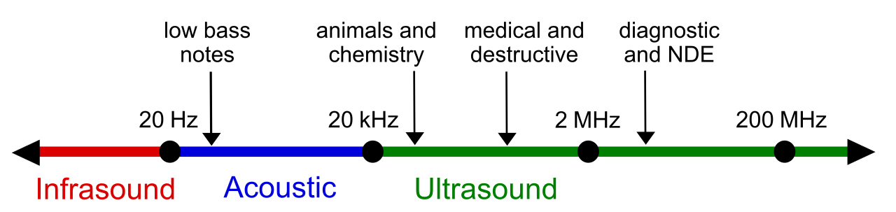
Credit: LightYear at English Wikipedia. Derivative work: Coolth, CC BY-SA 3.0 https://creativecommons.org/licenses/by-sa/3.0, via Wikimedia Commons
The frequency of a sound determines its pitch: High pitched sounds have high frequencies, and low-pitched sounds have low frequencies. However human sensitivity to sound is not uniform across all audible frequencies. In the image below, it can be seen that the hearing threshold (in decibels) for low frequency sound is higher than for high frequencies, although the pain threshold is relatively uniform across the audible range.
|
The relationship between frequency and pitch is perhaps most apparent in music. Most musical scales are based on the octave, a musical interval where the frequency of the higher note is twice that of the lower. Certain musical frequencies sound harmonious, or consonant when played together, while others sound discordant, or dissonant. Musical notes have overtones: vibrational frequencies that are integer multiples of the lowest (fundamental) frequency. Pleasant sounding combinations of notes tend to have overtones that are whole-number multiples of each other, while dissonant combinations are more irregular [3].
Resonant frequencies Musical instruments rely on resonance to amplify sound and produce specific notes. All objects have resonant, or |
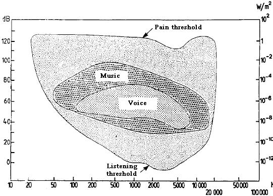
Hearing thresholds. Credit: Booby at English Wikibooks, public domain, via Wikimedia Commons
|
natural frequencies at which they tend to vibrate. When an object is subject to a driving force at its resonant frequency it will vibrate strongly, and a large amplitude oscillation can then result from a small driving force. In wind instruments, the resonant frequency is altered by varying the length of a vibrating air column, while in stringed instruments, the musician alters the length and tension of the strings. A visualisation of resonant frequencies is provided by the Chladni plate in the video below. A metal plate is sprinkled with sand and connected to a vibration generator. When the vibrational frequency matches one of the resonant modes of the plate, two-dimensional standing wave patterns form. The sand is shaken off
|
|
the antinodes, where the vibrations are strongest, and settles in the nodes where the vibrations cancel. At high frequencies, the patterns become more intricate. 18th century mathematician Sophie Germain’s work on elasticity contains a mathematical treatment of the Chladni plate. You can read about Germain in our blog.
Frequency is central to the research in the Mathematics of Waves and Materials group. Examples featured in our blog include the mathematical modelling of phononic crystals with frequency band gaps that enable the selective elimination of unwanted vibrational frequencies, and the design and realisation of metamaterials for the reduction of low frequency noise. |
[1] Mulligan, J. F. (1989) Heinrich Hertz and the Development of Physics, Physics Today 42 (3), 50
[2] Hogg, C., Neveu, M., Stokkan, K.-A., Folkow, L., Cottrill, P., Douglas, R., Hunt, D. M., and Jeffery, G. (2011) Arctic reindeer extend their visual range into the ultraviolet, Journal of Experimental Biology, 214, 2014-2019
[3] Ball, P. (2012) Why Dissonant Music Strikes the Wrong Chord in the Brain, Nature (London): n. pag. Web
G is for Ground Cloak
Over the past two decades, transformation-based techniques have enabled researchers to develop a range of engineered materials that can manipulate and control physical fields in new and exciting ways. We refer to these engineered materials as metamaterials where "meta" is a Greek word meaning beyond - i.e. a material beyond that of the natural world.
A particularly interesting example of a metamaterial is that of a cloaking device where a physical field is directed around a protected region without affecting the external field. As a result, any object placed inside the protected region is undetected! For example, we can protect and conceal an object that lies on a surface by covering it with the appropriate ground cloak, also referred to as a carpet cloak. A ground cloak is applicable to many physical systems, for example, a two-dimensional thermal ground cloak is simulated in Figure 1c.
A particularly interesting example of a metamaterial is that of a cloaking device where a physical field is directed around a protected region without affecting the external field. As a result, any object placed inside the protected region is undetected! For example, we can protect and conceal an object that lies on a surface by covering it with the appropriate ground cloak, also referred to as a carpet cloak. A ground cloak is applicable to many physical systems, for example, a two-dimensional thermal ground cloak is simulated in Figure 1c.
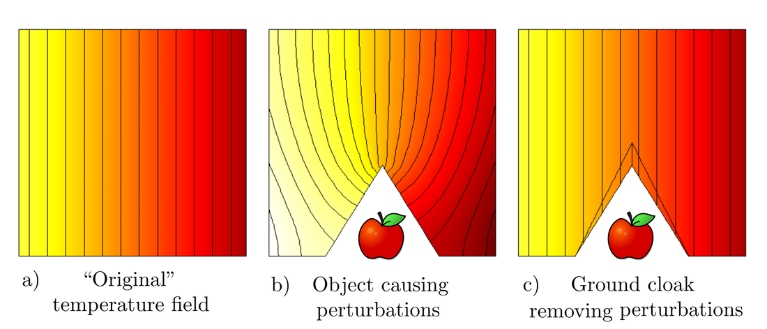
Figure 1: Simulations to show the effects of a thermal ground cloak.
Observe that, when part of the material domain is removed (or replaced by an object with different physical properties) unwanted perturbations form in the temperature field. A perturbation is any deviation of a field from its original state. However, in the final simulation we integrate a ground cloak into the material domain such that the perturbations are removed and the temperature field returns to its original state, as desired.
In order to achieve the desired effects we need the ground cloak to have specific physical properties. We can determine the physical properties of a ground cloak (and other metamaterials) through a process called transformation theory where we consider both a virtual and physical domain. The idea is as follows:
In order to achieve the desired effects we need the ground cloak to have specific physical properties. We can determine the physical properties of a ground cloak (and other metamaterials) through a process called transformation theory where we consider both a virtual and physical domain. The idea is as follows:
- Start with a virtual domain where the physical properties and physical fields are known.
- Define the region where the ground cloak (or an alternative metamaterial) is to be integrated.
- Apply a coordinate transformation to achieve the desired deformation in the physical domain.
- Calculate the physical properties of the metamaterial that will achieve the desired effects.
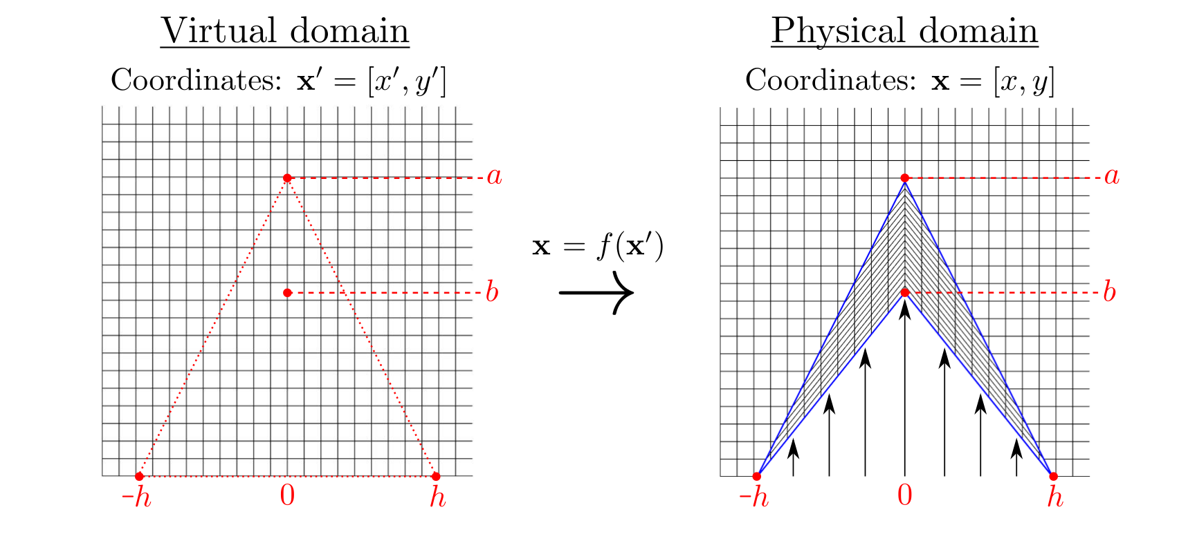
Figure 2: Illustration of a ground cloak transformation.
The appropriate ground cloak transformation is illustrated in Figure 2, where we wish to squeeze the red triangular region (in the virtual domain) into the blue arrowhead region (in the physical domain). The mapping is given by:
\begin{equation}
\begin{split}
x&=x' \\
y &= \dfrac{a-b}{a} y' + \dfrac{h - |x'|}{h}b
\end{split}
\end{equation}
Using this mapping we can calculate the physical properties of the ground cloak, however, the main difficulty encountered is that the calculated properties tend to be quite complex. Such designs are difficult to create with conventional materials and this is why we turn to engineered metamaterials where we can compose an artificial structure to account for spatial and directional dependencies.
As a result, three-dimensional ground cloaks have been realised for many physical systems, for example; a thermal ground cloak that controls a heat flux [1]; an acoustic ground cloak that controls sound waves [2]; and an optical ground cloak that controls electromagnetic waves at microwave frequencies [3].
E. Russell
[1] Yang, T., Wu, Q., Xu, W., Liu. D., Huang, L., Chen, F. (2016) A thermal ground cloak, Phys. Lett. A, 380 (7-8), 965-969.
[2] Zigoneanu, L., Popa, BI. & Cummer, S. (2014), Three-dimensional broadband omnidirectional acoustic ground cloak. Nature Mater, 13, 352–355.
[3] Ma, H., Cui, T. (2010) Three-dimensional broadband ground-plane cloak made of metamaterials, Nat Commun 1, 21.
[2] Zigoneanu, L., Popa, BI. & Cummer, S. (2014), Three-dimensional broadband omnidirectional acoustic ground cloak. Nature Mater, 13, 352–355.
[3] Ma, H., Cui, T. (2010) Three-dimensional broadband ground-plane cloak made of metamaterials, Nat Commun 1, 21.
H is for Helmholtz
|
Hermann von Helmholtz was a German physicist and scientific philosopher, who made significant contributions to several areas of science. Helmholtz was born it what was then Prussia, now Germany, in 1821. It would be thought that due to his significant contributions to the mathematical world, Helmholtz had studied mathematics as a student. However, due to financial pressures Helmholtz studied medicine, and taught himself mathematics and philosophy in his spare time [1]. Helmholtz went on to have an illustrious academic career in physics and philosophy, publishing many ground breaking papers and supervising famous students such as Max Planck and Heinrich Hertz, who went on to make significant contributions to science themselves.
You may be wondering why Hermann von Helmholtz has made this A-Z list. Well, Helmholtz performed research into wave sciences such as acoustics and electromagnetism, and his discoveries in these areas have led to some mathematical theories and engineering designs becoming his namesake. |
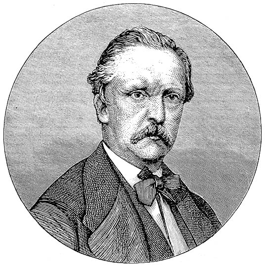
Hermann von Helmholtz. Credit: User Hedning on sv.wikipedia. Public domain, via Wikimedia Commons
|
Helmholtz performed experiments looking at electric currents, and concluded that the electronic oscillations were periodic in time. This observation can be generalised to say that any linear wave field periodic in time. This means, that if we were to consider a wave field in space and time, \( \phi (\mathbf{x},t)\), this can be written in terms of a time dependent periodic function
\begin{equation}
\phi(\mathbf{x},t) = \tilde {\phi}(\mathbf{x})\exp\{i 2\pi f t\}\tag{1},
\end{equation}
where \(f\) is the frequency of the wave. This solution form allows us to rewrite the wave equation in a simpler form
\begin{equation}
\nabla^{2}\phi - \frac{1}{c_{0}^{2}}\frac{\partial^{2}\phi}{\partial t^{2}} = 0 \implies \nabla^{2}\tilde{\phi} + \frac{\omega^{2}}{c_{0}^{2}}\tilde{\phi} = 0\tag{2},
\end{equation}
where \(c_{0}^{2}\)is the speed of sound and \( \omega = 2\pi f\). The resulting equation is known as the Helmholtz equation.
\begin{equation}
\phi(\mathbf{x},t) = \tilde {\phi}(\mathbf{x})\exp\{i 2\pi f t\}\tag{1},
\end{equation}
where \(f\) is the frequency of the wave. This solution form allows us to rewrite the wave equation in a simpler form
\begin{equation}
\nabla^{2}\phi - \frac{1}{c_{0}^{2}}\frac{\partial^{2}\phi}{\partial t^{2}} = 0 \implies \nabla^{2}\tilde{\phi} + \frac{\omega^{2}}{c_{0}^{2}}\tilde{\phi} = 0\tag{2},
\end{equation}
where \(c_{0}^{2}\)is the speed of sound and \( \omega = 2\pi f\). The resulting equation is known as the Helmholtz equation.

Brass Helmholtz resonator. Credit: brian0918, CC BY-SA 2.5: https://creativecommons.org/licenses/by-sa/2.5/deed.en via Wikimedia Commons
|
Helmholtz also performed research into acoustics, and performed experiments looking at acoustic resonators. A certain type of resonator, now known as a Helmholtz resonator was of particular interest to him. Helmholtz resonator describes a general theory for a resonator which had a long thin neck with a large cavity behind. At certain frequencies, depending on the dimensions of the resonator, resonance occurs. Two types of resonance can occur. The first kind can be seen by blowing across the top of a bottle, and when the air inside the bottle resonates, a louder sound is produced. This happens as cyclic fluctuations in the neck cause the pressure in the bottle to rise. The pressure is then released with the momentum carrying the air out, causing a pressure deficit inside the bottle - causing a rise in pressure and so on. These fast moving pressure oscillations generate noise. The second kind of resonance can be used to dampen sound. The air in the back of the cavity acts as a spring, as energy is lost in the thin neck due to viscous losses - the relationship between the neck and cavity dimensions determines the resonant frequency. These absorbing resonators are used to line jet engines to attenuate unwanted noise [2].
|
T. White
[1] Turner, R. S. (2008) Helmholtz, Hermann von, in Complete Dictionary of Scientific Biography, vol. 6, New York, NY: Charles Scribner's Sons, 241-253.
[2] Rienstra, SW & Hirschberg, A (2004) An introduction to acoustics. Technische Universiteit Eindhoven, Eindhoven.
[2] Rienstra, SW & Hirschberg, A (2004) An introduction to acoustics. Technische Universiteit Eindhoven, Eindhoven.
I is for inclusions
|
Inclusions are disjoint components within a multiphase material which have significantly different physical properties to those of the interstitial matrix phase. Usually, inclusions collectively make up a minority of the overall material's volume; often the symbol \(\phi\) or \(c\) is used to denote the volume fraction of the inclusion phase, the latter in analogy with concentration in chemistry. The purpose of the inclusion phase in material design is typically to enhance physical performance in a particular context, while adhering to practical constraints, for example, to increase the compressive or tensile strength while reducing the density. In this sense, it is possible to combine one or more types of inclusion within the matrix phase to create a hybrid composite material with improved functionality overall, compared to its individual ingredients.
The word "inclusion" suggests that a deliberate choice has been made to artificially include additional objects within the matrix material, but inclusions can also be unintentional, for |
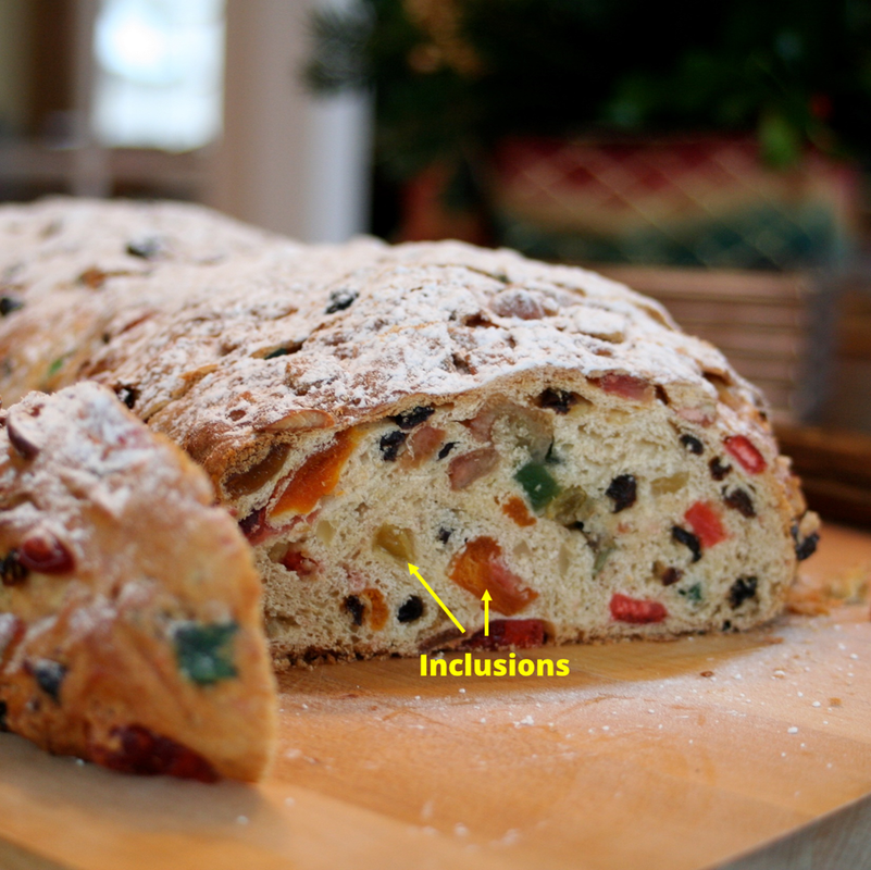
Figure 1. Credit: Whitney, CC BY 2.0, via Wikimedia Commons https://creativecommons.org/licenses/by/2.0
|
example impurities introduced in a manufacturing process. Inclusions also occur in natural materials, e.g. fossils, and flaws in diamonds. Inclusions in manufactured composite materials are typically solid or hollow particles, rods or fibres, or air bubbles, depending on the intended applications of the material. Note that each inclusion may itself be a multiphase object, for example a hollow glass sphere has an outer glass phase and an inner air phase. In general, symmetric shapes are preferred, particularly spherical or cylindrical inclusions, in order that the benefits are reasonably predictable and reliable over different samples of the same composite. Materials with symmetric and well-dispersed inclusions are also more amenable to study by mathematical modelling and computer simulation. Below we consider briefly the case of hollow spherical inclusions, assumed to be isolated from each other, under small strains.
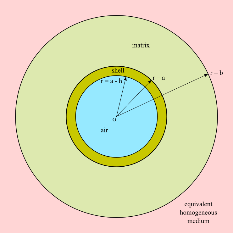
Figure 2. Schematic diagram of a hollow spherical inclusion.
|
A versatile mathematical model which represents the influence of spherical or cylindrical inclusions on a material's elastic properties is the Generalized Self-Consistent Method (Christensen & Lo, 1979), in which the model domain is composed of four phases as shown in figure 2. A single hollow inclusion is composed of an inner air (or void) phase, \(0 \leq r \leq a - h\), and an outer solid shell phase, \(a - h \leq r \leq a\). Solid inclusions may be considered as the special case \(h \to a\). The inclusion is surrounded by matrix material occupying \(a \leq r \leq b\), where for consistency we impose that \(a^3 / b^3 = c\), where \(c\) is the global volume fraction of inclusions. In this sense each inclusion is embedded within its own "share" of the matrix material, in the model. The region \(r \geq b\) is referred to as the equivalent homogeneous medium, and it is this phase which ultimately provides the effective properties
|
of the overall composite material, after the equations of linear elasticity have been solved in each phase subject to an applied far-field displacement and a strain energy equivalence condition, with appropriate boundary conditions at the interfaces \(r = a - h\), \(r = a\), and \(r = b\). Note that, in this model, the problem becomes dimensionless and the solutions can be expressed in terms of the inclusion's aspect ratio \(\eta = 1 - h/a\). Therefore, inclusions of different diameters but the same value of \(\eta\) have the same solution.
The method described above can be extended to account for materials containing multiple types of inclusion, with different diameters and shell stiffness properties for example, by volume averaging over the equivalent medium relating to each type (Bardella & Genna, 2001). Although the equations are algebraically cumbersome, in most applications a majority of the parameters can be considered as fixed, and the Young's modulus of the composite material can be computed as a function of the remaining free parameters. In the polydisperse case, it is important to have an accurate characterization of the inclusion phase via experimental imaging, although often a good approximation can be obtained via the volume-weighted mean diameter of the inclusions.
N. F. Morrison
[1] Bardella, L. & Genna, F. (2001) On the elastic behavior of syntactic foams, International Journal of Solids and Structures, 38, 7235-7260.
[2] Christensen, R. M. & Lo, K. H (1979) Solutions for effective shear properties in three phase sphere and cylinder models, Journal of the Mechanics and Physics of Solids, 27, 315-330.
[2] Christensen, R. M. & Lo, K. H (1979) Solutions for effective shear properties in three phase sphere and cylinder models, Journal of the Mechanics and Physics of Solids, 27, 315-330.
J is for Jacobian
Both linear and nonlinear multivariable functions can be thought of as transformations of space. The Jacobian of a function, named after the German mathematician Carl Jacobi, is a measure of how much the function stretches (or compresses) the original space. In particular, when making a change of variables, the Jacobian arises as a multiplicative factor within an integral to accommodate for the change of coordinates.
The Jacobian of a multivariable function \({f} : \mathbb{R}^n \rightarrow \mathbb{R}^m\), denoted by \(J\), is defined to be the determinant of the \(m \times n\) matrix, \(\mathbf{J}\), given by
\begin{equation}
\mathbf{J} = \left[ \begin{matrix} \dfrac{\partial f_1}{\partial x_1} & \cdots & \dfrac{\partial f_1}{\partial x_n} \\
\vdots & \ddots & \vdots \\ \dfrac{\partial f_m}{\partial x_1} & \cdots & \dfrac{\partial f_m}{\partial x_n}
\end{matrix} \right]\tag{1}
\end{equation}
This matrix represents what \(\boldsymbol{f}(\boldsymbol{x})\) looks like locally, as a linear transformation. We refer to \(\mathbf{J}\) as the Jacobian matrix of \(\boldsymbol{f}(\boldsymbol{x})\).
Linear Transformations
Linear transformations of space are unique in that they can be represented by matrices with scalar entries. For example, consider the linear function \(\boldsymbol{f} : \mathbb{R}^2 \rightarrow \mathbb{R}^2\) given by
\begin{equation}
\boldsymbol{f}(\boldsymbol{x}) = \left[ \begin{matrix} f_1(x,y) \\ f_2(x,y) \end{matrix} \right] = \left[ \begin{matrix} 3x + 2y \\ 2y \end{matrix} \right] = \left[ \begin{matrix} 3 & 2 \\ 0 & 2 \end{matrix} \right] \boldsymbol{x}\tag{2}
\end{equation}
where the \(2 \times 2\) matrix on the right-hand side of \((2)\) represents the linear transformation in matrix form.
Geometrically, the result of a linear transformation is that the grid lines remain parallel and evenly spaced. As a result, each unit square is mapped onto a parallelogram. For example, Figure 1 shows how \(\boldsymbol{f}(\boldsymbol{x})\) affects the grid lines of two-dimensional Euclidean space.
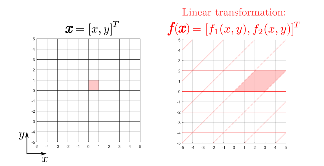
Linear transformation f(x), given in (1). Grid lines remain parallel and evenly spaced.
Note that, the transformed basis vector in the \(x\)-direction corresponds to the first column of the scalar matrix since
\begin{equation}
\boldsymbol{f}\left(\left[ \begin{matrix} 1 \\ 0 \end{matrix} \right]\right) = \left[ \begin{matrix} 3 & 2 \\ 0 & 2 \end{matrix} \right]\left[ \begin{matrix} 1 \\ 0 \end{matrix} \right] = \left[ \begin{matrix} 3 \\ 0 \end{matrix} \right]\tag{3}
\end{equation}
Similarly, the second column of the matrix corresponds to the transformed basis vector in the \(y\)-direction. These transformed basis vectors represent the edges of the parallelogram in transformed space. Therefore, the area of the red parallelogram in Figure 1 is given by the determinant of the scalar matrix, i.e.
\begin{equation}
\begin{matrix}
\text{area of} \\ \text{parallelogram}
\end{matrix} \ = \left| \begin{matrix} 3 & 2 \\ 0 & 2 \end{matrix} \right| = (3 \times 2) - (0 \times 2) = 6 \ \text{unit squares}\tag{4}
\end{equation}
In other words, the linear transformation in \((2)\) stretches any predefined area of the original space by a factor of 6.
This analogy is the motivation behind the Jacobian since, for linear transformations, finding the area of the relevant parallelogram is equivalent to finding the Jacobian. This is supported by the fact that, for linear transformations, the scalar matrix that represents the transformation is equivalent to its Jacobian matrix.
\begin{equation}
\boldsymbol{f}\left(\left[ \begin{matrix} 1 \\ 0 \end{matrix} \right]\right) = \left[ \begin{matrix} 3 & 2 \\ 0 & 2 \end{matrix} \right]\left[ \begin{matrix} 1 \\ 0 \end{matrix} \right] = \left[ \begin{matrix} 3 \\ 0 \end{matrix} \right]\tag{3}
\end{equation}
Similarly, the second column of the matrix corresponds to the transformed basis vector in the \(y\)-direction. These transformed basis vectors represent the edges of the parallelogram in transformed space. Therefore, the area of the red parallelogram in Figure 1 is given by the determinant of the scalar matrix, i.e.
\begin{equation}
\begin{matrix}
\text{area of} \\ \text{parallelogram}
\end{matrix} \ = \left| \begin{matrix} 3 & 2 \\ 0 & 2 \end{matrix} \right| = (3 \times 2) - (0 \times 2) = 6 \ \text{unit squares}\tag{4}
\end{equation}
In other words, the linear transformation in \((2)\) stretches any predefined area of the original space by a factor of 6.
This analogy is the motivation behind the Jacobian since, for linear transformations, finding the area of the relevant parallelogram is equivalent to finding the Jacobian. This is supported by the fact that, for linear transformations, the scalar matrix that represents the transformation is equivalent to its Jacobian matrix.
Nonlinear Transformations
Nonlinear transformations lead to grid lines that are no longer parallel and evenly spaced. As a result, the transformation of each unit square depends on its location, i.e. the Jacobian changes. This can be seen in Figure 2, where we consider the nonlinear function \(\boldsymbol{g} : \mathbb{R}^2 \rightarrow \mathbb{R}^2\) given by
\begin{equation}
\boldsymbol{g}(\boldsymbol{x}) = \left[ \begin{matrix} g_1(x,y) \\ g_2(x,y) \end{matrix} \right] = \left[ \begin{matrix} 1.25x + \sin(y) \\ \sin(x) + 1.25y \end{matrix} \right]
\tag{5}
\end{equation}
We see that the transformation compresses the blue unit square \((J<1)\) whereas the orange unit square is stretched \((J>1)\).
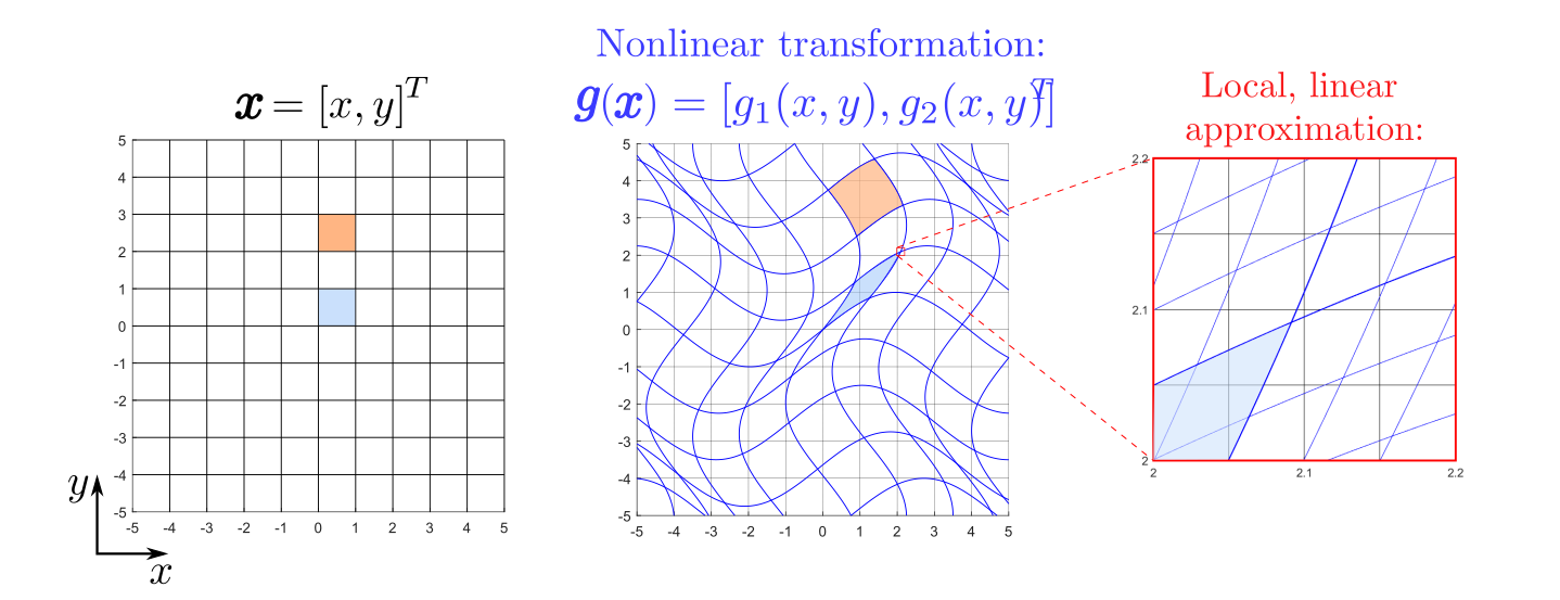
Figure 2. Nonlinear transformation g(x) given in (2). Note that, as we zoom in, the grid lines start to look more like a linear transformation.
As we zoom in on a small region of the transformed space, the grid lines start to look a lot more like a linear function. We use the Jacobian matrix of \(\boldsymbol{g}(\boldsymbol{x})\), given by
\begin{equation}
\mathbf{J} = \left[ \begin{matrix} \dfrac{\partial g_1}{\partial x_1} & \dfrac{\partial g_1}{\partial x_2} \\ \dfrac{\partial g_2}{\partial x_1} & \dfrac{\partial g_2}{\partial x_2} \end{matrix} \right] = \left[ \begin{matrix} 1.25 & \cos(y) \\ \cos(x) & 1.25 \end{matrix} \right]\tag{6}
\end{equation}
to represent what the transformation looks like locally, as a linear transformation. For example, in Figure 2 we have zoomed in on the top right corner of the transformed blue unit square. In the original space, this point is given by \([1,1]^T\). Therefore, the Jacobian of \(\boldsymbol{g}(\boldsymbol{x})\) around this point is approximately
\begin{equation}
J = \left| \begin{matrix} 1.25 & \cos(1) \\ \cos(1) & 1.25 \end{matrix} \right| \approx (1.25 \times 1.25) - (0.54 \times 0.54) \approx 1.27\tag{7}
\end{equation}
In other words, the nonlinear transformation in \((5)\) tends to stretch areas around the point \([1,1]^T\) by a factor of approximately 1.27. Therefore, for nonlinear transformations, we can think of the Jacobian as giving the best linear approximation of the distorted parallelogram near a given point.
\begin{equation}
\mathbf{J} = \left[ \begin{matrix} \dfrac{\partial g_1}{\partial x_1} & \dfrac{\partial g_1}{\partial x_2} \\ \dfrac{\partial g_2}{\partial x_1} & \dfrac{\partial g_2}{\partial x_2} \end{matrix} \right] = \left[ \begin{matrix} 1.25 & \cos(y) \\ \cos(x) & 1.25 \end{matrix} \right]\tag{6}
\end{equation}
to represent what the transformation looks like locally, as a linear transformation. For example, in Figure 2 we have zoomed in on the top right corner of the transformed blue unit square. In the original space, this point is given by \([1,1]^T\). Therefore, the Jacobian of \(\boldsymbol{g}(\boldsymbol{x})\) around this point is approximately
\begin{equation}
J = \left| \begin{matrix} 1.25 & \cos(1) \\ \cos(1) & 1.25 \end{matrix} \right| \approx (1.25 \times 1.25) - (0.54 \times 0.54) \approx 1.27\tag{7}
\end{equation}
In other words, the nonlinear transformation in \((5)\) tends to stretch areas around the point \([1,1]^T\) by a factor of approximately 1.27. Therefore, for nonlinear transformations, we can think of the Jacobian as giving the best linear approximation of the distorted parallelogram near a given point.
E. Russell
K is for Kelvin
William Thomson was a British mathematician and engineer born in Belfast. Thomson was awarded the title of Lord Kelvin, after a river which runs through Glasgow University, where he served as a professor for 52 years. Kelvin was a highly decorated mathematician, serving as the President of the Royal Society from 1890-1895.
Many mathematical and physical phenomena have been named after Kelvin in the years since his death. Most notably, the SI Unit for temperature is the kelvin. The kelvin measures temperature on the same scale as degrees Celsius, however the 'zero' has been shifted. For Celsius, we know that 0\(^{\circ}\)C is the freezing point of water. On the other hand, kelvin are measured such that 0 K is defined as absolute zero - the temperature at which particles achieve a minimum internal energy [1].
Many mathematical and physical phenomena have been named after Kelvin in the years since his death. Most notably, the SI Unit for temperature is the kelvin. The kelvin measures temperature on the same scale as degrees Celsius, however the 'zero' has been shifted. For Celsius, we know that 0\(^{\circ}\)C is the freezing point of water. On the other hand, kelvin are measured such that 0 K is defined as absolute zero - the temperature at which particles achieve a minimum internal energy [1].
|
The concept of absolute zero had been discussed before Kelvin, but a value had never been assigned. Kelvin considered the ideal gas law \(PV = nRT\), where \(P\) is a pressure, \(V\) is volume, \(n\) is the amount of a substance, \(R\) is the ideal gas constant and \(T\) is temperature. By considering the pressure in an ideal gas at ambient temperatures in Celsius - Kelvin exploited the linear relationship between \(P\) and \(T\) and, by tracing lines to find the point that \(P = 0\), discovered that the absolute zero temperature is -273.15\(^{\circ}\)C which is how 0 K is defined. Figure 1 shows how this tracing process can be done and how, for 3 different samples, the absolute zero temperature remains the same.
|
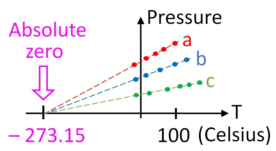
Figure 1. Plots of pressure vs temperature for three different gas samples at the same volume extrapolated to absolute zero. Credit: Guy Vandegrift, CC BY-SA 3.0, https://creativecommons.org/licenses/by-sa/3.0, via Wikimedia Commons
|
Another mathematical problem studied by Kelvin, as well as a previous A-Z entry - Hermann von Helmholtz, is that of Kelvin-Helmholtz instabilities. These specific instabilities are seen when there is a velocity difference across the interface between two fluids. The interface between the two fluids is pulled up and spirals, as can be seen in Figure 2, where wave-like

Stratocumulus stratiformis clouds showing Kelvin-Helmholtz instability. Credit: Krister Valtonen, CC BY 3.0, https://creativecommons.org/licenses/by/3.0, via Wikimedia Commons
|
structures have formed in the clouds. Kelvin-Helmholtz instabilities can be seen in the atmosphere and ocean waves as well as in the atmospheres of other planets [2].
Helmholtz was the first to recognise that instabilities can form as a result of shear flow, but it was Kelvin who first posed and fully solved the problem of a linear instability of a vortex sheet between two layers of fluid with different densities. The instabilities form as the kinetic energy from the relative movement of the two layers is converted into potential energy used to raise or lower a fluid, causing the vortical wave shapes to form in the wake of the shear flow [3]. T. White
|
[1] Erlichson, H. (2001) Kelvin and the absolute temperature scale, Eur. J. Phys, 22(4), 325.
[2] Vujinovic, A. and Rakovec, J. (2015) Kelvin-Helmholtz Instability, Univerza v Ljubljani Fakulteta za Matematiko in Fiziko.
[3] Drazin, P.G (1970) Kelvin–Helmholtz instability of finite amplitude, J. Fluid Mech, 42(2), 321-335.
[2] Vujinovic, A. and Rakovec, J. (2015) Kelvin-Helmholtz Instability, Univerza v Ljubljani Fakulteta za Matematiko in Fiziko.
[3] Drazin, P.G (1970) Kelvin–Helmholtz instability of finite amplitude, J. Fluid Mech, 42(2), 321-335.
L is for Lamb Waves
Sir Horace Lamb, FRS (1849-1934) was a British applied mathematician, responsible for ground-breaking research work in the fields of fluid and solid mechanics. His outstanding contributions extend to other fields such as electromagnetics, and more generally outside academic research, the education system at both national and institutional levels [1]. Lamb was also an excellent lecturer and writer and some of his original books still remain very relevant and widely used today, as is the the case with Hydrodynamics, which was originally published in 1895.
Lamb has a particularly strong connection with Manchester since he was born in Stockport, and also the University of Manchester (when he arrived it was still Owens College) where he was a professor for over three decades and held the Beyer Chair of Applied Mathematics. During his time at Manchester he published much of his original work and interacted with other great scientists such as the great fluid dynamicist Osborne Reynolds.
It is worth mentioning that following Lamb, the Beyer Chair has been held by many great mathematicians including Sir James Lighthill and more recently one of MWM's founders, Professor Ian David Abrahams. Furthermore, there is a chair named after Lamb in Manchester, and some of his original furniture is still in the Mathematics department. The Sir Horace Lamb Chair remains occupied by its first holder, Professor Oliver Jensen.
One of the problems that attracted the attention of Lamb was understanding the different modes of vibration of an (infinite) elastic plate, which back then was already of practical interest to the seismology community.
The strategy was to look for travelling wave solutions of the equations of linear elasticity (see E is for Elasticity, above), together with a traction-free boundary condition (see B is for Boundary Conditions) on the top and bottom of the plate (the other two spatial dimensions are assumed to be infinite). The problem reduces to finding solutions to particular types of dispersion equations, which relate a given wave's frequency (see F is for Frequency) to its wavenumber. These equations are of paramount importance in the study of wave physics since they encompass all of the information to understand the wave motion in a particular system.
For an elastic plate of thickness \(d\) with material constants \(\lambda, \mu, \rho\) and angular frequency \(\omega\), the Lamb wave dispersion equations are explicitly given by
\begin{equation}
\frac{\tanh{(\gamma_t d/ 2)}}{\tanh{(\gamma_l d/2)}} = \frac{4 \gamma_l \gamma_t k^2}{(k^2 + \gamma_t^2)^2}, \qquad\textrm{(Symmetric)} \quad\tag{1a}
\end{equation}
\begin{equation}
\frac{\tanh{(\gamma_t d/ 2)}}{\tanh{(\gamma_l d/2)}} = \frac{(k^2 + \gamma_t^2)^2}{4 \gamma_l \gamma_t k^2}, \qquad\textrm{(Anti-symmetric)}\quad\tag{1b}
\end{equation}
with
\begin{equation}
\gamma_l^2 = k^2 - k_l^2 = k^2 -\frac{\rho \omega^2}{\lambda + 2\mu}, \qquad \gamma_t^2 = k^2 - k_t^2 = k^2 - \frac{\rho \omega^2}{\mu} \tag{2}.
\end{equation}
Solutions to (\(1a\)) correspond to symmetric (extensional) modes \(S_n\) and solutions to (\(1b\)) describe anti-symmetric (flexural) modes \(A_n\), see Figure 1. The waves associated with the modes of vibration (\(S_n, A_n\)) are commonly referred to as Lamb Waves. The subscript \(n\) is a positive integer that characterizes a given mode. Except for \(n=0\), the existence of a given mode and its associated velocity is highly dependent on the frequency of excitation (and plate thickness), as illustrated in Figure 2.

Figure 1: A0 (left) and S0 (right) modes propagating in an elastic plate. Animations created by Dr. Noé Jiménez, many thanks for the permission to use these here! For more animations check out his personal website: https://nojigon.webs.upv.es/simulations_waves.php
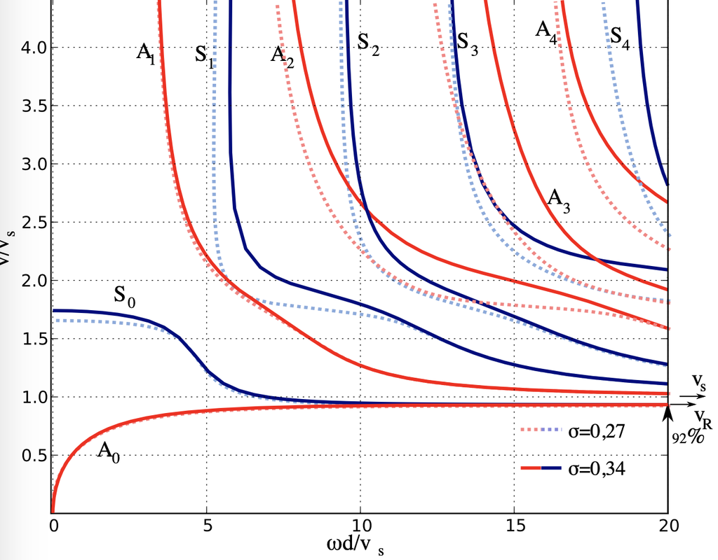
Figure 2: Some dispersion curves Sn, An, of the Lamb dispersion relation for two distinct material parameters (in terms of Poisson's ratio σ). The vertical axis denotes the wave velocity and the horizontal axis the frequency. Credit: Svebert, CC BY 3.0 https://creativecommons.org/licenses/by/3.0, via Wikimedia Commons
Equations (\(1\)) are highly non-linear equations in the complex plane for the wavenumber \(k\) and as a result, difficult to solve. Particular limits can be taken for useful insights e.g. for short waves compared to the thickness of the plate, (\(1a\)) reduces to the Rayleigh dispersion relation. However, analytical solutions to these equations are in general not readily available and the use of numerical techniques are usually adopted (e.g. Figure 3). It is remarkable to note how much harder Lamb's task was to analyse the main properties of these equations and how clear the original paper [2] reads given his limited computing resources.

Figure 3: A numerical visualization in k-space of the symmetric equation (1a) with \(d\) = 2, \(k_l\) = 1.2 and \(k_t\) = 2. Much easier to identify the roots now than in 1916...
The original paper has currently got over 2000 citations, and more than 80% are from the current century. This is mainly due to the many computational and experimental advances throughout the years, from which many applications of Lamb waves have arisen, particularly in ultrasonic non destructive testing. Lamb waves remain subject of current research and have recently motivated interesting metamaterial structures [3, 4]. Lastly, the study of Lamb guided elastic waves with application to hidden tamper detection was the PhD thesis subject from former MWM member Dr. Robert Davey which can be found in [5].
E. Garcia-Neefjes
[1] Launder, B. (2017) Horace Lamb… and how he found his way back to Manchester, Comptes Rendus Mécanique, 345(7), 477-487.
[2] Lamb, H. (1917) On waves in an elastic plate, Proceedings of the Royal Society of London. Series A, Containing Papers of a Mathematical and Physical Character, 93(648), pp. 114-128.
[3] Williams, E. G., Roux, P., Rupin, M. & Kuperman, W. A. (2015) Theory of multiresonant metamaterials for A0 Lamb waves, Physical Review B, 91(10), p. 104307.
[4] Zhao, D.-G., Li, Y. & Zhu, X.-F. (2015) Broadband Lamb Wave Trapping in Cellular Metamaterial Plates with Multiple Local Resonances, Scientific Reports, 5(1), p. 9376.
[5] Davey, R. (2018) An improved approach to the modelling of guided elastic waves with application to hidden tamper detection. University of Manchester
M is for Metamaterials
|
In 1968, Viktor Veselago published a paper describing the possibility of negative refraction [1]. He proposed that this would require a medium in which permittivity, ε, and magnetic permeability, μ, were negative. These properties describe how a material responds to applied electric and magnetic fields, and are positive in conventional materials. Veselago predicted that such a material could have new and interesting optical properties, such as a reverse Doppler effect. Veselago’s work went largely unnoticed until the late 1990s, when John Pendry and co-workers created two designs; a periodic mesh of very thin wires with negative ε [2, 3]; and an array of split-ring cylinders with negative μ [4]. Building on Pendry’s and Veselago’s work, Smith and co-workers made a composite structure in which both ε and μ were negative in the microwave region, resulting in a negative refractive index in that frequency range [5]. Smith called his periodoc array a
|
A split ring resonator array, part of a 'left-handed' metamaterial [6]. Credit: [email protected] (Glenn research contact), Public domain, via Wikimedia Commons
|
metamaterial, a term already being used to describe new and unusual materials. This opened up the field of metamaterials into what has become a very broad area of research.
The properties of metamaterials result from their structures, rather than their chemical composition. Metamaterials are composed of subunits (sometimes referred to as meta-atoms), on a sub-wavelength scale, which are usually periodically arranged. The geometry, size and relative positions of the subunits confer properties to the bulk metamaterial that are not found in the constituent materials. The prefix meta comes from the Greek, meaning “after”, or “beyond”, and metamaterials can be considered to have properties beyond those of conventional materials. In particular, the sub-wavelength microstructures of metamaterials allow them to interact with waves in unusual ways. The early examples from Pendry and Smith, were active in the microwave region of the electromagnetic spectrum, but the field has broadened rapidly to include elastic, seismic, acoustic and mechanical metamaterials. As the wavelengths of different types of waves vary hugely in scale, so the scale and design of metamaterial subunits is equally wide-ranging.
The properties of metamaterials result from their structures, rather than their chemical composition. Metamaterials are composed of subunits (sometimes referred to as meta-atoms), on a sub-wavelength scale, which are usually periodically arranged. The geometry, size and relative positions of the subunits confer properties to the bulk metamaterial that are not found in the constituent materials. The prefix meta comes from the Greek, meaning “after”, or “beyond”, and metamaterials can be considered to have properties beyond those of conventional materials. In particular, the sub-wavelength microstructures of metamaterials allow them to interact with waves in unusual ways. The early examples from Pendry and Smith, were active in the microwave region of the electromagnetic spectrum, but the field has broadened rapidly to include elastic, seismic, acoustic and mechanical metamaterials. As the wavelengths of different types of waves vary hugely in scale, so the scale and design of metamaterial subunits is equally wide-ranging.
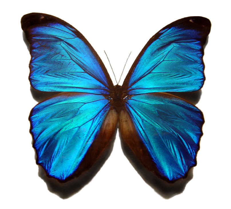
Blue morpho butterfly. Credit: Gregory Phillips, CC BY-SA 3.0
|
Although metamaterials are sometimes described as having properties not found in nature, several examples of natural materials have been proposed as metamaterials. They range in scale from the very small to the very large. For example, the wings of the morpho butterfly get their distinctive blue colour not from pigmentation, but from the interaction of light with a microstructure consisting of a grating of ribs [7]. A recent study showed that the scales on moth wings are a natural acoustic metamaterial, absorbing a broad range of ultrasound frequencies, and camouflaging the moth from echolocating bats [8]. At the larger end of the scale, periodic arrangements of trees in forests have been discussed as resonant metamaterials, attenuating seismic waves at specific frequencies between 15 and 150 Hz [9].
|
Synthetic metamaterials are equally varied. Since their unusual properties arise from their geometries and not their composition, a wide range of materials have been used to achieve them. These include paper (where the metamaterial structure is achieved by origami), Lego® bricks (whose modular nature lends itself to building periodic structures), bubbly water, and 3-D printed media [10-13]. The structural design is mathematically modelled using coordinate transformation methods. The process is outlined in the image below: the desired wave manipulation is first defined in terms of a spatial, or coordinate transformation. Then the physical properties of a material capable of achieving this wave distortion are calculated. These properties are often challenging to achieve: a feature common to many metamaterials is the possession of properties with negative values, where a positive value is the norm in a conventional material. Examples include negative Poisson’s ratio, refractive index, effective bulk modulus and mass density.
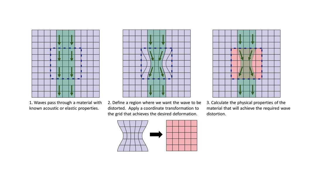
Schematic for the stepwise process of transformation acoustics and transformation elasticity.
Transformation optics was pioneered by Smith and Pendry in the development of the first metamaterial cloak, which was capable of concealing a small copper cylinder from microwave frequency waves by bending the waves around the object [14]. While optical and acoustic cloaking remain key areas of research in metamaterials, many other practical uses have emerged. These include acoustic lensing and sound attenuation, and the selective elimination of unwanted frequencies
|
(the frequency band gap, discussed here). Other notable applications include a metamaterial film which exhibits radiative cooling, metamaterial biosensors, and synchrotron generation on a metasurface [15-17].
Acoustic and elastic metamaterials are a strong research theme in the Waves and Materials group. In this blog post you can read about a metamaterial that halves the effective speed of sound, while maintaining an acoustic impedance close to that of air, allowing significant space savings in noise cancellation devices (see also A is for Acoustics, above). Read more about our work in this and related fields here. |

Cross-section of 3D printed metamaterial resonators capable of attenuating noise at half the frequency compared to a conventional resonator of equivalent size
|
LEGO® is a trademark of the LEGO Group of companies which does not sponsor, authorize or endorse this site
[1] Veselago, V. G. (1968). "The electrodynamics of substances with simultaneously negative values of ε and μ" Soviet Physics Uspekhi, 10(4), 509-514
[2] Pendry, J. B., Holden, A. J., Stewart, W. J., & Youngs, I. (1996) "Extremely Low Frequency Plasmons in Metallic Mesostructures." Physical Review Letters, 76(25), 4773-4776.
[3] Pendry, J. B., Holden, A. J., Robbins, D. J., & Stewart, W. J. (1998) "Low frequency plasmons in thin-wire structures." Journal of Physics: Condensed Matter, 10(22), 4785-4809.
[4] Pendry, J. B., Holden, A. J., Robbins, D. J., & Stewart, W. J. (1999) "Magnetism from conductors and enhanced nonlinear phenomena." IEEE Transactions on Microwave Theory and Techniques, 47(11), 2075-2084.
[5] Smith, D. R., & Kroll, N. (2000). "Negative Refractive Index in Left-Handed Materials." Physical Review Letters, 85(14), 2933-2936.
[6] Wilson, J. D. and Z. D. Schwartz (2005) "Multifocal flat lens with left-handed metamaterial." Applied Physics Letters 86(2): 021113.
[7] Gralak, B., Tayeb, G. & Enoch, S. (2001). "Morpho butterflies wings color modeled with lamellar grating theory." Optics Express, 9(11), pp. 567-578.
[8] Neil, T. R., Shen, Z., Robert, D., Drinkwater, B. W., & Holderied, M. W. (2020) "Moth wings are acoustic metamaterials." Proceedings of the National Academy of Sciences, 117(49), 31134.
[9] Colombi, A., Roux, P., Guenneau, S., Gueguen, P., & Craster, R. V. (2016) "Forests as a natural seismic metamaterial: Rayleigh wave bandgaps induced by local resonances." Scientific Reports, 6(1), 19238.
[10] Kamrava, S., Mousanezhad, D., Ebrahimi, H., Ghosh, R., & Vaziri, A. (2017) "Origami-based cellular metamaterial with auxetic, bistable, and self-locking properties." Scientific Reports, 7(1).
[11] Celli, P., & Gonella, S. (2015) "Manipulating waves with LEGO® bricks: A versatile experimental platform for metamaterial architectures." Applied Physics Letters, 107(8), 081901.
[12] Luan, P.-G. (2019) "Bubbly Water as a Natural Metamaterial of Negative Bulk-Modulus." Crystals, 9(9), 457.
[13] Rowley, W. D., Parnell, W. J., Abrahams, I. D., Voisey, S. R., Lamb, J., & Etaix, N. (2018) "Deepening subwavelength acoustic resonance via metamaterials with universal broadband elliptical microstructure." Applied Physics Letters, 112(25), 251902.
[14] Schurig, D., Mock, J. J., Justice, B. J., Cummer, S. A., Pendry, J. B., Starr, A. F., & Smith, D. R. (2006) "Metamaterial Electromagnetic Cloak at Microwave Frequencies." Science, 314(5801), 977.
[15] Zhai, Y., Ma, Y., David, S. N., Zhao, D., Lou, R., Tan, G., Yang, R. & Yin, X. (2017) "Scalable-manufactured randomized glass-polymer hybrid metamaterial for daytime radiative cooling." Science, 355(6329), 1062.
[16] Salim, A., & Lim, S. (2018) "Recent advances in the metamaterial-inspired biosensors". Biosensors and Bioelectronics, 117, 398-402.
[17] Henstridge, M., Pfeiffer, C., Wang, D., Boltasseva, A., Shalaev, V. M., Grbic, A., & Merlin, R. (2018) "Synchrotron radiation from an accelerating light pulse." Science, 362(6413), 439.
N is for Neutral Inclusions
In material science, we refer to a material domain as a matrix and an inclusion as an object inside the matrix with different material properties. Inclusions are typically used in designs to enhance the physical performance of the material. For more information see I is for inclusions, above.
|
On the other hand, sometimes engineers are forced to incorporate inclusions into their designs - adding windows along the sides of commercial aircraft for instance. Unfortunately, in these cases, the physical performance of the design can be compromised. Therefore, we also want to be able to add an inclusion to a matrix which does not alter the physical performance. We call such inclusions neutral inclusions. Neutral inclusions were first introduced by Mansfield in 1953 for holes in a sheet. Mansfield demonstrated that, for a plane sheet under a particular loading state, certain reinforced holes (inclusions) may be made which do not alter the stress distribution in the main body of the sheet (the matrix). He called these reinforced holes neutral holes [1]. |
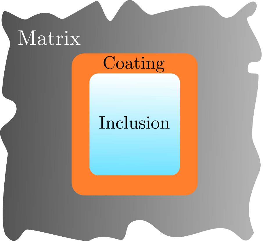
Figure 1: Concept of a neutral inclusion
|
The idea, illustrated in Figure 1, is to surround each inclusion with a specific coating that causes the physical fields in the matrix to return to their original state, i.e. the state when the inclusion is not present. The required properties of the coating depend on both the matrix and the inclusion. When the necessary properties are satisfied, the inclusion and its coating are collectively referred to as a neutral inclusion.
In the following example we consider a neutral inclusion inside a steady-state temperature field.
In the following example we consider a neutral inclusion inside a steady-state temperature field.
Neutral inclusion - thermal conductivity example
In this example we consider a two-dimensional problem and assume steady-state conditions. In particular, we consider the linear temperature field in Figure 2, where the black lines represent lines of constant temperature, referred to as isotherms. The temperature field in Figure 2 has the form \(T(x)=\alpha x\) for some constant \(\alpha\).
Note that, due to the steady-state assumption, the only material property that affects the temperature field is the thermal conductivity, denoted \(k\). Furthermore, we assume that the thermal conductivity of each component in the following problem is isotropic (independent of direction) and homogeneous (independent of position), i.e. \(k\) is a scalar.
Let the matrix in Figure 2, 3 and 4 have conductivity \(k_m\) and let the circular inclusion in Figure 3 have conductivity \(k_i\), where \(k_i \neq k_m\). Notice that, when the inclusion is embedded in the matrix, the field is altered and is no longer linear. We refer the these alterations as perturbations.

Figure 2: Linear temperature field with respect to x
|
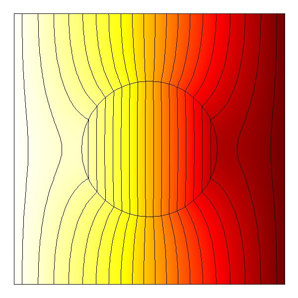
Figure 3: Inclusion leading to perturbations.
|
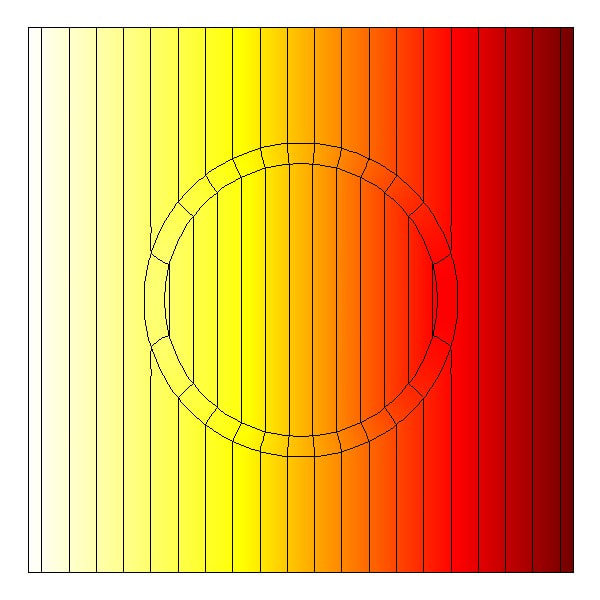
Figure 4: Neutral inclusion leading to unperturbed field in the matrix.
|
We aim to remove the perturbations from the matrix in Figure 3 (and recover the linear temperature field) by surrounding the inclusion with a coating with conductivity \(k_c\), as illustrated in Figure 5.
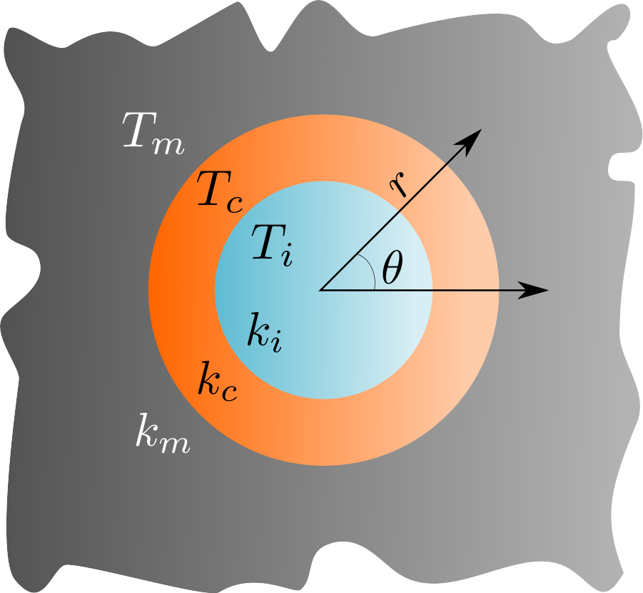
Figure 5: Configuration for neutral inclusion in polar coordinates,
x = [r,θ].
|
By enforcing perfect contact conditions across each interface (continuity of heat flux and temperature) we find that, in order for \(T_m\) to be linear with respect to \(x\), we must satisfy
\begin{equation} D^2 = \dfrac{(k_m-k_c)(k_i+k_c)}{(k_i-k_c)(k_m+k_c)} \qquad \text{where} \qquad D= \dfrac{r_i}{r_c}\tag{1} \end{equation} where \(r_i\) and \(r_c\) represent the radius of the inclusion and coating respectively. Therefore, the two radii and the conductivities of all three components are dependent on each other. The workings for this are shown in a previous blog post. Figure 5 shows the resulting temperature fields when the condition in (1) is satisfied. We see that the temperature field in the matrix is unperturbed and once again linear with respect to \(x\) as required. |
E. Russell
[1] E. H. Mansfield (1953) Neutral holes in plane sheet - reinforced holes which are elastically equivalent to the uncut sheet, The Quarterly Journal of Mechanics and Applied Mathematics, 6(3), 370–378
O is for Optimisation
When we think about enhanced performance materials, we typically think qualitatively. Depending on the intended application, a "good" material should be strong, or lightweight, or recoverable, or breathable, flexible, insulating, green, cheap, etc., or (usually) a combination of several such adjectives simultaneously. To decide whether one candidate material is superior to another in a particular context, and furthermore to define an optimal material, it is necessary to make these considerations quantitative, in terms of the mathematical and chemical properties of materials but also in terms of the metrics being used to assess performance and suitability.
Where possible, the desired behaviours of an enhanced material should be condensed into an appropriate mathematical combination of specific physical properties, for example Young's modulus, mass density, damage tolerance, porosity, stiffness, conductivity, carbon content, cost, etc. Such a combination is called an objective function; in general mathematical terms, an optimal solution to a problem minimizes (or maximizes) the associated objective function, and a procedure for calculating optimal solutions is known as an optimization algorithm.
Each of the physical material properties on which an objective function depends may itself be a function of several numerical input parameters which can be varied in the design process. For example, the macroscale mass density of a composite material is a function of the mass densities of each of its separate homogeneous components, and of the proportions (volume fractions) of those components in the composite.
To define an optimization problem [1], we need an objective function \(f: \mathbb{R}^n \to \mathbb{R}\), expressed mathematically in terms of a vector \(\mathbf{x}\) of \(n\) input parameters (or decision variables), \(\mathbf{x} = (x_1, \dots, x_n)\), and we need to specify regional constraints (e.g. upper and lower bounds) on the parameters, \(\mathbf{x} \in \Omega \subseteq \mathbb{R}^n\). Additionally we should identify any functional constraints on combinations of parameters - for example the proportions of the components in a composite material should add up to at most 100%. Functional constraints can be represented in the form \(\mathbf{g}(\mathbf{x}) = \mathbf{b}\) where \(\mathbf{g}: \mathbb{R}^n \to \mathbb{R}^m\) and \(\mathbf{b} \in \mathbb{R}^m\). Inequality constraints are often handled via the addition of slack variables, i.e. a scalar constraint \(g(\mathbf{x}) \leq b\) might be recast as \(g(\mathbf{x}) + y = b\) where \(y\) is a slack variable subject to \(y \geq 0\). The set of possible values of parameters which satisfy the regional and functional constraints is called the feasible set.
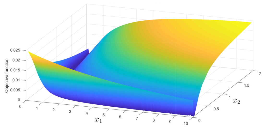
Figure 1. An example objective function plotted against two parameters.
Fig. 1 shows an example where the objective function \(f\) depends on two parameters \(x_1\) and \(x_2\). In this example the problem was to minimize \(f\) subject to the regional constraints \(0 \leq x_1 \leq 10\) and \(0 \leq x_2 \leq 2\). The surface displayed is a smoothed triangulation of approximately 10000 evaluations of \(f\). The outcome in this particular problem is that there is a nearly flat hyperbolic valley (the dark blue colour in the image) which asymptotes to the \(x_1\) and \(x_2\) axes, and the optimal solution is the extremity of this valley in the \(x_2\) direction. Had the valley been exactly flat, a multitude of optimal solutions would have existed, and the flat valley would have been an example of a Pareto optimum [2], i.e. a curve or "frontier" along which no significant improvement can be made. In such cases a re-examination of the definition of the objective function may allow for a particular optimal solution to be identified.
In general, the choice of optimization algorithm is typically guided by the technical details of the problem, such as the mathematical form of \(f\) and the constraints, but also by practical considerations such as the runtime required to calculate each evaluation of the objective function. It is not always obvious which algorithm is most suitable, and it is a relatively "young" subject; even for fully linear optimization problems, an efficient and practical polynomial-time algorithm was not established until 1984 [3].
In some industrial applications, each iteration can require outputs from a finite element simulation or some other time consuming calculation, and therefore an algorithm which involves a surrogate model may be preferable. The idea of surrogate optimization is to interpolate from a small number of evaluations of the real objective function \(f\), generate an approximating function \(h\) which fits the available data on \(f\) but is far quicker to evaluate, and use the minima/maxima of \(h\) to guide the search for the true minima/maxima of \(f\) itself.
N. F. Morrison
[1] Bazaraa, M. S., Jarvis, J. J. & Sherali, H. D. (1990) Linear programming and network flows. 2nd ed. New York: Wiley.
[2] Debreu, G. (1954) Valuation equilibrium and Pareto optimum. Proceedings of the National Academy of Sciences of the United States of America, 40(7), pp. 588-592.
[3] Karmarkar, N. K. (1984) A new polynomial-time algorithm for linear programming. Combinatorica, 4(4), pp. 373-395.
[2] Debreu, G. (1954) Valuation equilibrium and Pareto optimum. Proceedings of the National Academy of Sciences of the United States of America, 40(7), pp. 588-592.
[3] Karmarkar, N. K. (1984) A new polynomial-time algorithm for linear programming. Combinatorica, 4(4), pp. 373-395.
P is for Phase Portrait
Being able to visualise complex functions is a very useful skill in most fields of mathematics. When working with complicated functions of complex variables, it is often difficult to know instinctively what and where the interesting features are. Such features, including zeros, singularities, branch cuts, saddle points etc., are a vital part in analysing and understanding the function. You may want to find regions of analyticity, check where a pole is in relation to an integration contour or determine what is the chosen branch of a multi-valued function.
Fundamentally, every complex number \(z\) is written uniquely in Cartesian form in terms of two real numbers \(x\in\mathbb{R}\) and \(y\in\mathbb{R}\) such that \(z=x+iy\in\mathbb{C}\) where \(i=\sqrt{-1}\) is the imaginary unit. Here \(x\) is called the real part \(\operatorname{Re}(z)\) and \(y\) is the imaginary part \(\operatorname{Im}(z)\). Similarly, every complex function \(f(z)\) can also be decomposed this way, \(f(z)=u(x,y)+iv(x,y)\) where \(u=\operatorname{Re}(f(x+iy))\) and \(v=\operatorname{Im}(f(x+iy))\) are functions of \(x\) and \(y\).
Besides the Cartesian representation, complex numbers also have a polar representation \(z=re^{i\theta}\) where \(r\in\mathbb{R}\) is the absolute value \(|z|\) and \(\theta\in\mathbb{R}\) is the complex argument \(\arg(z)\). The phase of a complex number is given by \(e^{i\theta}\) and lies on the unit circle of the complex plane for every complex number. This extends to complex functions as well. We define the complex phase by \(\psi_f(z)=\frac{f}{|f|}\).
We can visualise \(\psi_f\) using phase portraits which map the unit circle range onto a circular *HSV colour scheme. We utilise MATLAB and a collection of code written by Elias Wegert to plot these phase portraits. This code is freely available from MATLAB's community website. Also see the associated book by the same author for a comprehensive guide on this subject [1]. As a demonstration, consider the identity function \(f(z)=z\) which is displayed on Figure 1.
Zeros: We say that the function \(f\) has a zero of order \(n>0\) at the point \(z_0\), if \(f(z)\approx C(z-z_0)^n\) when \(z\approx z_0\) for some constant \(C\). On a \(z\) circle centred on \(z_0\) with a suitably small radius, the phase of \(f\) will cycle through the colour scheme \(n\) times. This is clearly shown in Figure 1, which cycles through the colour scheme anticlockwise about \(z=0\) once. This is because the function \(f(z)=z\) has a zero of order \(1\) at \(z_0=0\). Similarly, Figure 2 displays a zero of order \(2\) (meaning 2 colour cycles) from the function \(f(z)=z^2\).
Zeros: We say that the function \(f\) has a zero of order \(n>0\) at the point \(z_0\), if \(f(z)\approx C(z-z_0)^n\) when \(z\approx z_0\) for some constant \(C\). On a \(z\) circle centred on \(z_0\) with a suitably small radius, the phase of \(f\) will cycle through the colour scheme \(n\) times. This is clearly shown in Figure 1, which cycles through the colour scheme anticlockwise about \(z=0\) once. This is because the function \(f(z)=z\) has a zero of order \(1\) at \(z_0=0\). Similarly, Figure 2 displays a zero of order \(2\) (meaning 2 colour cycles) from the function \(f(z)=z^2\).
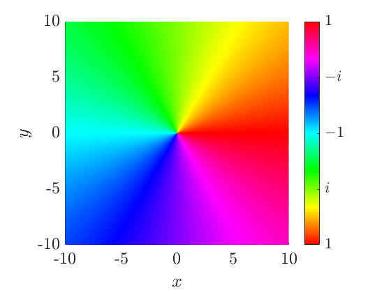
|
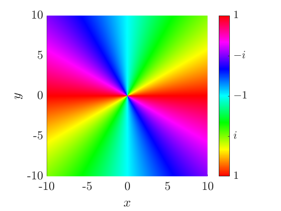
|
|
Figure 1. Phase portrait of the identity function \(f(z)=z\) with a zero of order \(1\) at \(z_0=0\).
|
Figure 2. Phase portrait of the function \(f(z)=z^2\) with a zero of order \(2\) at \(z_0=0\).
|
Poles: The function \(f\) has a pole of order \(n>0\) at the point \(p_0\), if \(f(z)\approx \frac{C}{(z-p_0)^n}\) when \(z\approx p_0\) for some constant \(C\). On a small circle about \(p_0\), the phase of \(f\) will cycle through the colour scheme \(n\) times but in the opposite direction compared to zeros. We see this in Figure 3 because the considered function \(f(z)=\frac{1}{z}\) has a pole of order \(1\) at \(p_0=0\) and hence it cycles through the colour scheme clockwise about \(z=0\) once. Functions with multiple zeros and/or poles will share the same behaviour of the colour scheme in local regions about the individual features (see Figure 4 for example).
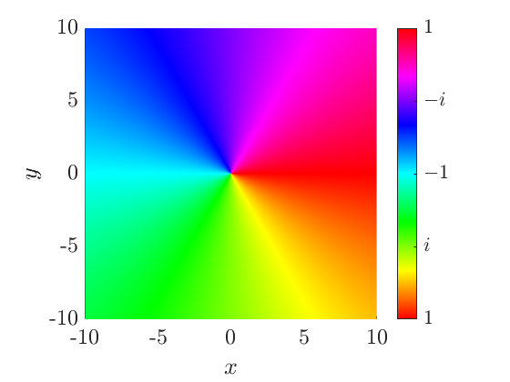
Figure 3. Phase portrait of the simple pole function \(f(z)=\frac{1}{z}\) with a pole of order \(1\) at \(p_0=0\).
|
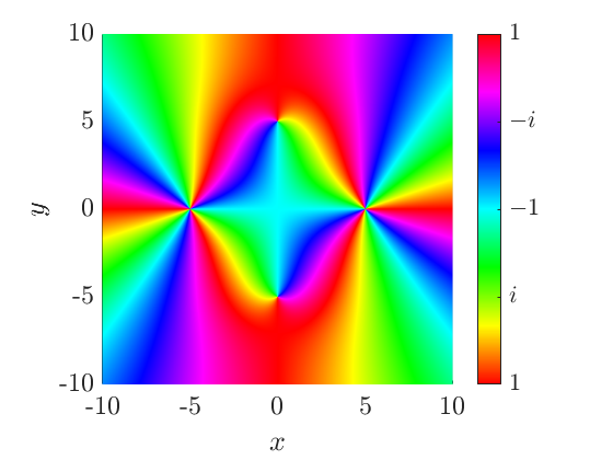
Figure 4. Phase portrait of the function \(f(z)=\frac{(z^2-25)^3}{z^2+25}\). How many zeros and poles are there? Where are they? What are their orders?
|
Branch cuts: In complex analysis, a function \(f\) is multi-valued if there exists a branch point \(b_0\) such that,
$$f(b_0+\epsilon e^{i\theta})\neq f(b_0+\epsilon e^{i(\theta+2\pi)})$$
for some \(0<\epsilon\ll1\) and an arbitrary angle \(\theta\). Most of the time when working with multi-valued functions, we need to use branch cuts to restrict the local angle \(\theta\) about \(b_0\) and force the functions to be single-valued. In phase portraits, these branch cuts show themselves as lines of discontinuity.
By default, elementary multi-valued functions such as \(\sqrt[n]{z}\) and \(\log(z)\), are defined in MATLAB using the principal branch, i.e. the branch cut is on the negative real axis and the local angle is restricted to the range \((-\pi,\pi]\). For example, the default definition of \(f(z)=\sqrt{z}\) is displayed on Figure 5.
Let us say that we wanted the branch cut to be rotated anticlockwise by \(\theta_0\), such that the local angle is restricted a new range given by \((-\pi+\theta_0,\pi+\theta_0]\). MATLAB can implement this with a simple trick. For example, take the square-root function \(f(z)=\sqrt{z}\), multiply the square-root argument by \(e^{i\theta_0}e^{-i\theta_0}\) and move the first part outside. This leads to the equivalent definition \(f(z)=e^{\frac{i\theta_0}{2}}\sqrt{e^{-i\theta_0}z}\) which, for \(\theta_0=\frac{\pi}{2}\), has the phase portrait given by Figure 6.
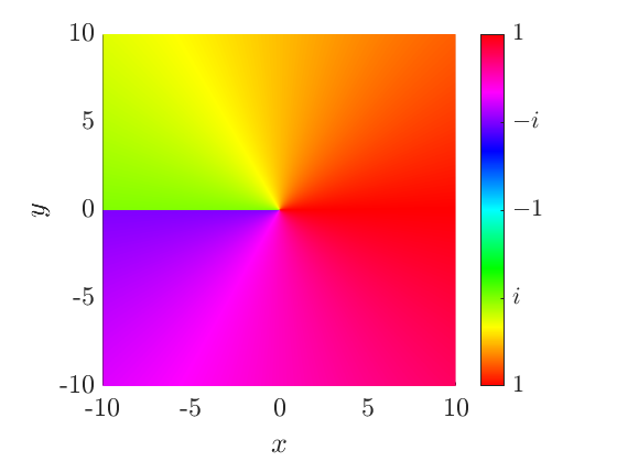
Figure 5. Phase portrait of the square root principal branch \(f(z)=\sqrt{z}\). Here the square root's argument is restricted to the range \((-\pi,\pi]\).
|
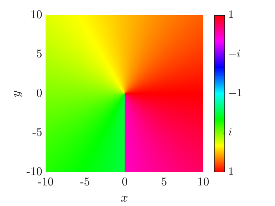
Figure 6. Phase portrait of the square root function \(f(z)=\sqrt{z}=e^{\frac{i\pi}{4}}\sqrt{-iz}\) with a different branch cut definition. Here the square root's argument is restricted to the range \(\left(-\frac{\pi}{2},\frac{3\pi}{2}\right]\).
|
This trick works with any \(n^{\text{th}}\) root and logarithmic function and even works on functions with multiple branch cuts. For instance, different definitions of the double square-root \(f(z)=\sqrt{z+1}\sqrt{z-1}\),
$$i\sqrt{1+z}\sqrt{1-z},\ \ \sqrt{i(z+1)}\sqrt{-i(z-1)},\ \ e^{\frac{i\pi}{4}}\sqrt{z+1}\sqrt{-i(z-1)},$$
all describe the same double square-root but all have very different phase portraits.
Real-life examples: In modern research, phase portraits help a great deal in understanding and interpreting the increasingly difficult complex functions that arise in mathematics. This includes identifying and classifying features such as zeros, singularities and cuts among others. A phase portrait is also a medium that tells us how computers view the complex function in question.
In reference [2], we used the mapping
$$g(z)=\cos^{-1}\left(\frac{k_1}{k_2}\cos(z)\right)$$
to transform Sommerfeld integrals between two wavenumbers \(k_1\) and \(k_2\). Normally, the phase portrait of \(g(z)\) is given by Figure 7, but we needed a special definition of this mapping to have the right properties for the transform. In the end, this special branch would have a phase portrait given by Figure 8 (see appendix A of [2] for more details).
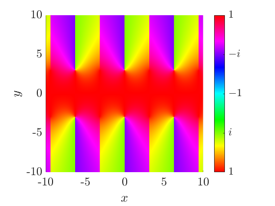
Figure 7. Phase portrait of the default definition of the mapping \(g(z)=\cos^{-1}\left(\frac{k_1}{k_2}\cos(z)\right)\) where \(\frac{k_1}{k_2}=\frac{1}{10}\).
|
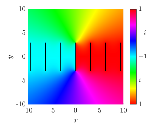
Figure 8. Phase portrait of the special branch definition of the mapping \(g(z)=\cos^{-1}\left(\frac{k_1}{k_2}\cos(z)\right)\) where \(\frac{k_1}{k_2}=\frac{1}{10}\). The black lines indicate branch cuts. Note how this definition is not periodic like the default one.
|
In a unique way, phase portraits are considered to be the mathematical equivalent of a calendar model. Since 2011, the Institute of Applied Analysis at TU Bergakademie Freiberg has released calendars containing a gallery of the phase portraits of many different complex functions. This shows that phase portraits are not only useful in analysing complex functions, but can also output some incredibly pretty and colourful pictures.
M. A. Nethercote
*Hue, saturation, value, sometimes known as HSB (hue, saturation, brightness). Hue is expressed as a numerical value between 0 and 360°.
[1] Wegert, E. (2012) Visual Complex Functions, Basel, Birkhauser.
[2] Nethercote, M. A., Assier, R. C. and Abrahams, I. D. (2020) High-contrast approximation for penetrable wedge diffraction, IMA Journal of Applied Mathematics, 85(3), 421-466.
[1] Wegert, E. (2012) Visual Complex Functions, Basel, Birkhauser.
[2] Nethercote, M. A., Assier, R. C. and Abrahams, I. D. (2020) High-contrast approximation for penetrable wedge diffraction, IMA Journal of Applied Mathematics, 85(3), 421-466.
Q is for Quarter Wavelength Resonator
A Quarter Wavelength Resonator (QWR) is a side branch of an acoustic duct, designed to attenuate sound which has a wavelength four times the length of the resonator. Consider a wave propagating down the main acoustic duct, and diverted into the QWR. The propagating wave then reflects off the back of the QWR and back into the main duct. Now, if the propagating wave has a wavelength four times longer than the side branch, then as the wave propagates back into the acoustic duct, it will be out of phase with the waves propagating in the duct by exactly half its wavelength. This means that the two waves are perfectly out of phase and will cancel each other out. This behaviour is described in the animation in Figure 1.
Figure 1. Schematic of a quarter wavelength resonator (QWR).
This is all well and good, but in practice if we want to attenuate sound this way, the side branches would have to be a quarter of the length of the desired sound wave, which can be meters in length, making this method impractical. In [1] a metamaterial (see M is for Metamaterial) approach to the QWR is taken with the goal of reducing the size of side branch required to attenuate a specific frequency. This is done by adding some periodic structure into the side branch which changes the effective properties of the QWR in order to attenuate alternative frequencies in the same sized branch. More specifically, the case considered is to halve the length of the branch required to attenuate a specific frequency. This can be done by reducing the effective speed of sound in the branch by half, which reduces the period of the wave inside the side branch, meaning that in the same sized branch the attenuated frequency is halved.
|
The new QWR was designed to have a periodic elliptical microstructure inside the side branch, which can be seen in Figure 2. There are 4 shape parameters which describe the ellipse: \(A_x, A_y\) describe the dimensions of a unit cell in which one ellipse sits on the middle, with radial parameters \(a_x, a_y\). Two techniques are applied to determine the required shape parameters in order to halve the speed of sound inside the side branch. The first of these techniques is similar to that used to create a ground cloak (see G is for Ground Cloak), where a virtual domain is created with the desired physical properties. The virtual domain is then transformed to fit the physical domain with the free variables - in this case density and bulk modulus - being transformed in order to maintain the desired speed of sound. This transformation therefore gives us the required physical properties which need to be satisfied in the cavity achieve the desired speed of sound.
|
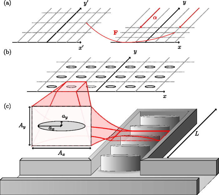
Figure 2. Design of the QWR microstructure. From [1].
|
The second technique, homogenisation, allows us to design a periodic structure which gives the required effective properties. In the design of the QWR it was decided that the cavity would include a periodic elliptical microstructure and homogenisation was used in order to determine the effective properties of the resonant tube with the microstructure embedded.
Due to the periodic nature of the microstructure we can consider a unit cell within the cavity which contains a single ellipse. Then by considering the behaviour of sound in this unit cell we can generalise to the overall microstructure to find the effective properties in terms of the dimensions of a unit cell. We can then cross reference to calculate the elliptical parameters required to achieve the desired effective density and bulk modulus given by the transformation acoustics. We call these properties 'effective' as it generalises the microstructure to be a homogeneous material with constant properties unlike the physical material which has two phases (air and polymer) with different properties.
In Figure 3 we see the experimental results comparing two different metamaterial designs with a standard QWR. The two designs can be seen in Figure 4. The first has the ellipse in the centre of the branch with the second having the ellipse split in half. All three resonators are the same length. We can see that the peak in transmission loss is shifted to the left by half.
In Figure 3 we see the experimental results comparing two different metamaterial designs with a standard QWR. The two designs can be seen in Figure 4. The first has the ellipse in the centre of the branch with the second having the ellipse split in half. All three resonators are the same length. We can see that the peak in transmission loss is shifted to the left by half.

Figure 3. Experimental results comparing transmission loss across a range of frequencies for metamaterial designs A and B with a standard QWR, C. From [1].
|
This is equivalent to saying the new QWR attenuated sound twice the wavelength of a standard resonator, effectively making the branch a \(\frac{1}{8}^{\text{th}}\) wavelength resonator. Thus making it easier to attenuate sounds of lower frequency in the same amount of space. It can also be seen that by arranging the periodic structure differently between the red and green lines, the resonator can become more (or less) effective.
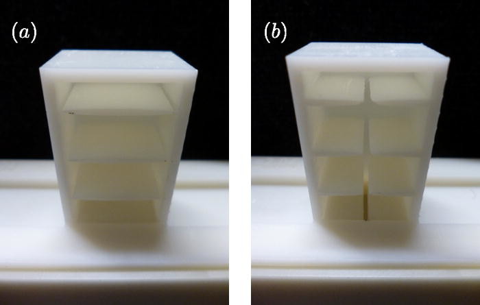
Figure 4. 3D printed metamaterials A and B. From [1].
T. White
|
[1] Rowley, W. D., Parnell, W. J., Abrahams, I. D., Voisey, S. R., Lamb, J., & Etaix, N. (2018) "Deepening subwavelength acoustic resonance via metamaterials with universal broadband elliptical microstructure." Applied Physics Letters, 112(25), 251902.
R is for Resonance
Resonance is an everyday occurrence (e.g. a swing or a guitar) nevertheless it is linked to some counter-intuitive notions. Resonance can occur whenever there are waves or vibrations, here we will concentrate on acoustic resonance but will also use mechanical resonance as a simple example. The key notion is that of natural frequency of a system.
This can be used to build up large oscillations by forcing the system at natural frequency and this is what we will concentrate on here. Alternatively resonance can be used to create a standing wave (which has on average no net propagation of energy). This is exploited in musical instruments where a string or a pipe (which can be open or closed) will create a standing wave at the natural frequency and its harmonics. The creation of the standing wave can be explained by constructive and destructive interference.
Resonators are commonly used as unit cells in metamaterials to create interesting effects (see M is for Metamaterials, above).
|
Ideal Pendulum
Consider an ideal pendulum (string length \(L\)) and set it swinging by applying some force to it. What time does it take to come back? It seems that it should depend on the force that is applied. But in fact it does not. (This property allows for pendulum clocks to keep time, and in fact modern quartz watches also rely on resonance). The well-known formula for the time taken for the pendulum (for moderate amplitudes) to do a full cycle is \[T=2\pi \sqrt{\frac{L}{g}}\] where \(g\) is the local acceleration of gravity. So the amplitude of the oscillation does not influence the time taken for a full swing, we say the system has a natural |
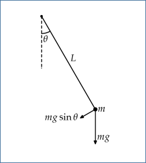
Figure 1. A simple pendulum
|
frequency. This has profound consequences, if a force is applied at equal time intervals \(T\) then the applied force will add to the force that the pendulum already possesses and increase the amplitude of oscillations. This is called resonance. Resonance is highly dependent on the frequency of the periodic forcing matching the natural frequency of the system, and leads to increased amplitude of the oscillations. If the force is applied at other times then at least some of the energy will cancel. At resonance all the energy is directed at increasing the amplitude.
Acoustic Resonance
Acoustic resonance is similar: when a wine glass is hit a sound will be produced at a certain frequency, the natural frequency of the wine glass. The frequency does not depend on the force of the hit. Forcing the system in this case can be done by playing sound of the same natural frequency. The vibrations can get so high as to break the glass.
Acoustic resonance is similar: when a wine glass is hit a sound will be produced at a certain frequency, the natural frequency of the wine glass. The frequency does not depend on the force of the hit. Forcing the system in this case can be done by playing sound of the same natural frequency. The vibrations can get so high as to break the glass.
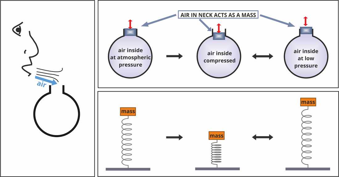
Figure 2. Schematic of a Helmholz resonator.
|
A Helmholtz resonator (see H is for Helmholtz, above) is used to produce acoustic resonances, and the workings of it can be compared to that of a spring and mass system. It is simple to conduct an experiment by blowing over the neck of a glass bottle, see Figure 2. The force of the blow forces the air in the neck of the bottle (which acts as a mass) to move down, creating an increase of pressure inside the cavity (which acts as a spring). The increased pressure then forces the air in the neck to move back up, the momentum of which moves it past the
|
equilibrium point causing the gas in the cavity to have lower pressure. This draws the air back in, and so it repeats. A surprisingly low and loud sound is the result. The resonance frequency can be changed by changing the volume of air in the bottle (i.e. the spring stiffness). In an experiment this can be easily done by putting some water in the bottle.
A. Kisil
S is for Strain ENergy Function
Squeezing a bottle of water, kneading dough, sprinting, and smiling. These are a minute selection of the seemingly infinite number of ways that objects, including the human body, are deformed, or strained, when subjected to a load. Sometimes these changes are temporary, as the object returns to its initial configuration once a load has been released. However, these changes can instead be permanent, altering the behaviour of the object for good. For example, when human skin is cut during surgery, it is subjected to high loads that causes long-lasting scarring which changes how the affected area reacts to being stretched or compressed.
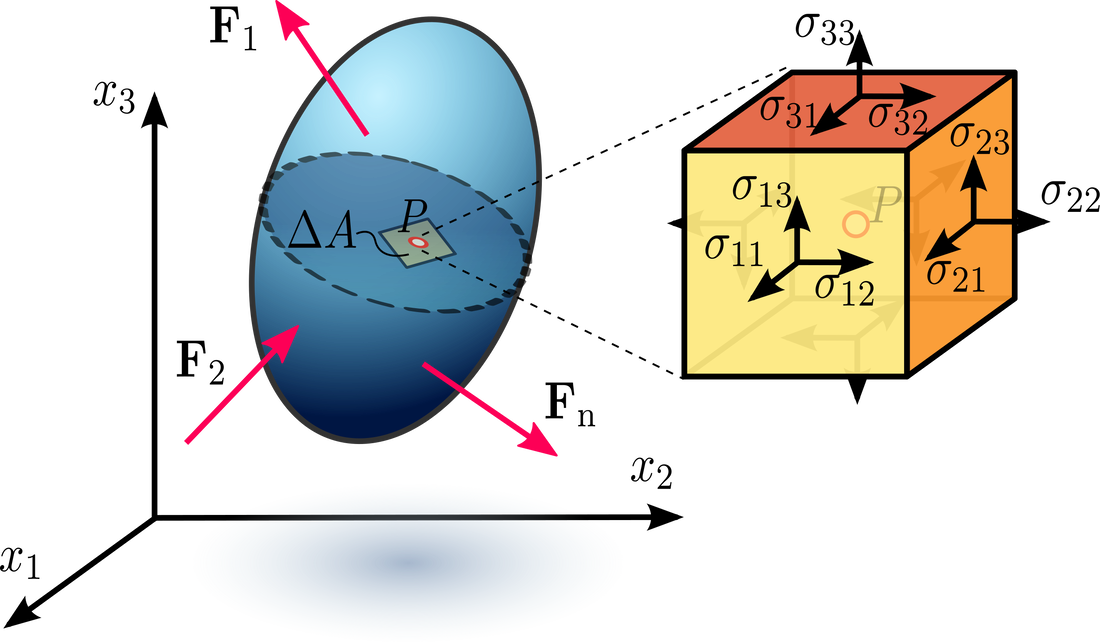
Figure 1: Stress tensor. For \(\sigma_{ij}\), \(i\) represents the direction normal (i.e. perpendicular) to the face of the cube and \(j\) represents the direction the stress is acting in. Credit: Sanpaz, CC BY-SA 3.0 , via Wikimedia Commons.
If we are to understand the world we live in, therefore, it is important that we can describe the mechanical behaviour of deformed materials mathematically. To describe the internal forces acting in a body as it is strained, we introduce the physical quantity stress, which is a measure of force over area. For small strains, the relationship between stress and strain is commonly given by
\begin{equation}
\label{linearStressStrainRelation}
\boldsymbol{\sigma} = \mathbf{c}\boldsymbol{\epsilon}\tag{1},
\end{equation}
where \(\boldsymbol{\sigma}\) is the second-order Cauchy stress tensor, Figure 1, \(\mathbf{c}\) is the fourth-order elasticity tensor, and \(\boldsymbol{\epsilon}\) is the second-order strain tensor [1]. In \eqref{linearStressStrainRelation}, the elasticity tensor linearly transforms the strain tensor into the stress tensor. I am sure you will have heard of Hooke's law before, and \eqref{linearStressStrainRelation} is just a generalisation of Hooke's law in three dimensions [2], accounting for the effect of both tensile strains and shear strains, Figure 2, on the body.
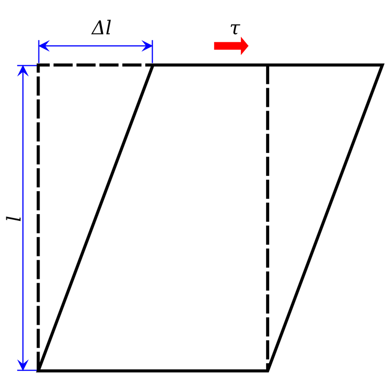
Figure 2: Shear stress. In tensile stress, the stress acts perpendicular to the face of the material, but shear stresses act parallel to the face. Credit: Krish-navedala, CC0, via Wikimedia Commons
This linear relationship between stress and strain is a reasonable approximation to make at small strains, but not for larger ones. Therefore, if we want to study the mechanical behaviour of an object at larger strains, we must derive a new relation between stress and strain. One method of creating this relation is to use the field of continuum mechanics and, specifically, the theory of hyperelasticity to relate stress and strain using a strain-energy function (SEF) that quantifies the amount of potential energy stored in a deformed object due to the strain applied.
SEFs have been used to model the mechanical behaviour of rubber-like materials and fibre-reinforced biological soft tissues such as skin, arteries, and tendons. Soft tissues display highly non-linear stress-strain behaviour, Figure 3, demonstrating the necessity for deriving a non-linear SEF to quantify the stress-strain relationship.
The laws of physics we use to describe the universe must be the same at all places and times. Therefore, the SEF must remain invariant under a change of reference frame, i.e. a coordinate transformation. Thus, we can write the SEF as a function of other quantities associated with the strain that are invariant under a change of coordinates. Furthermore, the exact form of the SEF is dependent on the symmetry properties of the material itself. An isotropic material possesses the same mechanical behaviour in all directions, but the mechanical behaviour of a transversely isotropic material is only symmetric for rotations around a preferred direction, \(\mathbf{M}\). The SEF for a transversely isotropic material is, therefore, dependent on the strain applied and \(\mathbf{M}\). While the full SEF for a transversely isotropic material contains three strain invariants and two pseudoinvariants that account for \(\mathbf{M}\), it is common in the literature to write the SEF for an incompressible (volume-preserving) material as a function of just the isotropic invariant \(I_1\) and the pseudoinvariant \(I_4\). For example, the SEF, \(W\), for a transversely isotropic version of the widely used Holzapfel-Gasser-Ogden model [3] is
\begin{equation}
\label{HGOTIversion}
W(I_1, I_4) = \frac{c}{2}(I_1-3) + \frac{k_1}{k_2}(\exp(k_2(I_4-1)^2)-1)\tag{2},
\end{equation}
where \(c\) and \(k_1\) are stress-like model parameters and \(k_2\) is a dimensionless model parameter. In order to calculate the stress, \eqref{HGOTIversion} is substituted into the following constitutive equation:
\begin{equation}
\boldsymbol{\sigma} = -p\mathbf{I} + 2\mathbf{F}\frac{\partial W}{\partial I_1} \mathbf{F}^\textrm{T} + 2\mathbf{F}\left(\frac{\partial W}{\partial I_4}\mathbf{M}\otimes\mathbf{M}\right)\mathbf{F}^\textrm{T}\tag{3},
\end{equation}
where \(-p\) is a Lagrange multiplier introduced because of the incompressibility of the material; \(\mathbf{F}\) is a measure of the deformation known as the deformation-gradient; \(^\textrm{T}\) represents the transpose of a tensor; and \(\otimes\) represents the tensor product.

Figure 3: Typical stress-strain behaviour of soft tissues. At small strains, fibrils of the stiff protein collagen are crimped, or wavy, and slack so the tissue is compliant (A). As the strain increases, fibrils gradually become straight and tauten (B) and as more fibrils tauten the tissue stiffens rapidly (C).
J. Haughton
[1] Chou, P. C. & Pagano, N. J. (1992) Elasticity: tensor, dyadic, and engineering approaches. New York: Dover.
[2] Gould, P. L. & Feng, Y. (1994) Introduction to linear elasticity. vol. 2. New York: Springer.
[3] Holzapfel, G. A., Gasser, T. C. & Ogden, R. W. (2000) A new constitutive framework for arterial wall mechanics and a comparative study of material models. Journal of elasticity and the physical science of solids 61(1), pp1-48.
T is for Tissues
In 2006 the Department of Health reported that there are more than 200 musculoskeletal conditions, which account for approximately 30% of GP consultations in England [1]. An understanding of the mechanical behaviour of connective tissues such as ligaments, tendons, bone and cartilage, is key to the development of effective treatment, and preventative measures. Mathematical modelling is an essential tool in achieving such an understanding. Within the Waves and Materials group, research has centred on the modelling of bone and tendons, and on imaging methods such as X-Ray computed tomography [2-4].
Connective tissues are inhomogeneous, multi-phase biological materials with a broad range of functions. The physical properties of connective tissues vary widely depending on function, and many types have been identified. The majority can be loosely categorised into three main types: loose, dense and specialised. Loose connective tissues include adipose (fat) tissue and reticular tissues (fibrous tissues found around organs including the kidneys and liver). Tendons and ligaments are classified as dense connective tissues, and blood and bone as specialised.
While differing in properties and function, connective tissues share the same principal components: cells, and an extracellular matrix consisting of fibres and ground substance. Ground substance is an amorphous, gel-like fluid containing water and large hydrophilic organic molecules. In bone, the ground substance is mineralised. The fibres in the extracellular matrix are composed mainly of the proteins collagen and elastin. Because of their multi-component nature and their anisotropy, the mechanical properties of connective tissues are complex. For example, the strength of a bone may vary along its length, and its response to stress will depend on the direction in which the force is applied.
|
Viscoelastic Behaviour
A characteristic common to connective tissues is that they are viscoelastic, meaning that their mechanical behaviour is time-dependent [5]. In a perfectly linear elastic material, the relationship between stress, \(\sigma\) (an applied force per unit area) and strain, \(e\) (the amount of deformation in the material) is \(\sigma = Ee\), where \(E\) is the elastic modulus of the material (see E is for Elasticity, above). For a viscoelastic material, stress is a function of both the strain and the strain rate: \(\sigma = \sigma (e, \dot e)\). The characteristics of viscoelastic materials include viscoelastic creep, where a material exhibits a gradual deformation and recovery in response to an applied or removed load; stress relaxation, a gradual reduction in stress under a constant strain; and hysteresis in the stress-strain curve, where energy is dissipated as heat during deformation, so that the loading and unloading curves do not follow the same path. These are illustrated in figure 1, and more fully described here. |
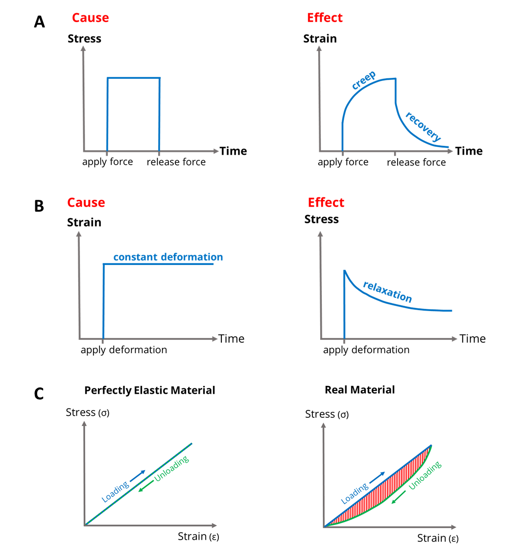
Figure 1. A: Graphs of stress and strain vs time illustrating viscoelastic creep and recovery under an applied load. B: Graphs of strain and stress vs time illustrating stress relaxation under an applied strain. C: Graphs of stress vs strain for loading and unloading in a perfectly elastic (left) and a viscoelastic (right) material.
|
Tendons
Tendons and ligaments are dense connective tissues. Tendons connect bone to muscle and transmit forces between them, while ligaments provide stability, connecting bones together (figure 2). Injuries to tendons are slow to heal, and damaged tendons rarely return to full mechanical strength, making a full understanding of tendon mechanics desirable [6]. Tendon fibres have a hierarchical structure consisting of fascicles: bundles of collagen fibrils, which are many times thinner than spider silk, and crimped (figure 3). As tendons are stretched, the fibrils begin to straighten, taking up strain when they are fully extended. Individual fibrils within a fascicle have different critical lengths at which they are fully
Tendons and ligaments are dense connective tissues. Tendons connect bone to muscle and transmit forces between them, while ligaments provide stability, connecting bones together (figure 2). Injuries to tendons are slow to heal, and damaged tendons rarely return to full mechanical strength, making a full understanding of tendon mechanics desirable [6]. Tendon fibres have a hierarchical structure consisting of fascicles: bundles of collagen fibrils, which are many times thinner than spider silk, and crimped (figure 3). As tendons are stretched, the fibrils begin to straighten, taking up strain when they are fully extended. Individual fibrils within a fascicle have different critical lengths at which they are fully
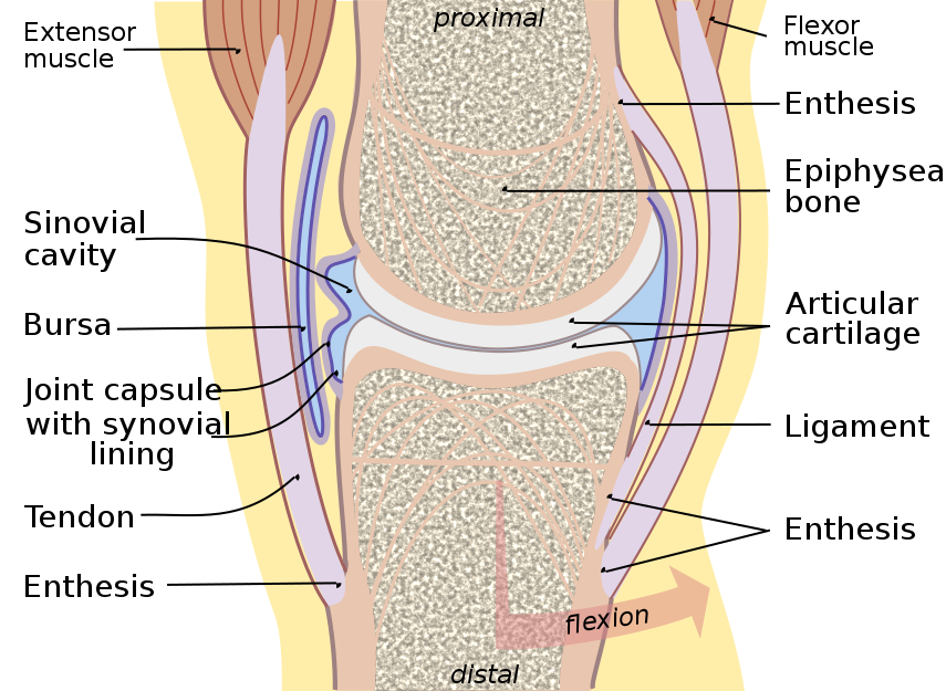
Figure 2. Joint cross-section. Credit: Madhero88, CC BY-SA 3.0
|
extended, and tendon stiffness will increase as more fibrils reach their critical length and take up strain [7].
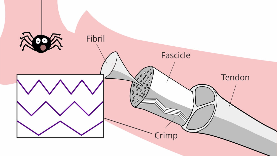
Figure 3. Schematic diagram showing the hierarchical structure of a tendon.
|
Recent work within the Waves and Materials group, describing a new model for tendon behaviour that takes account of viscoelastic creep in fibrils, is summarised in this illustrated video:
[1] Department of Health. A Join Responsibility: Doing it Differently, 270211. London: DH Publications; 2006.
[2] Parnell, W.J., Vu, M.-B., Grimal, Q. and Naili, S. (2012) "Analytical methods to determine the effective mesoscopic and macrosopic elastic properties of cortical bone". J. Biomechanics and Modelling in Mechanobiology, 11, 883-901 (doi:10.1007/s10237-011-0359-2)
[3] Shearer, T. (2015) “A new strain energy function for the hyperelastic modelling of ligaments and tendons based on fascicle microstructure”. J. Biomech., 48, 290-297. (doi: 10.1016/j.jbiomech.2014.11.031)
[4] Shearer, T., Rawson, S., Castro, S.J., Balint, R., Bradley, R.S., Lowe, T., Vila-Comamala, J., Lee, P.D. and Cartmell, S.H. (2014) "X-ray computed tomography of the anterior cruciate ligament and patellar tendon", Muscle, Ligaments and Tendons Journal 4, 238-244. (doi:10.11138/mltj/2014.4.2.238)
[5] Özkaya N., Leger D., Goldsheyder D., and Nordin M. "Mechanical Properties of Biological Tissues" In: Özkaya N, Leger D, Goldsheyder D, Nordin M, editors. Fundamentals of Biomechanics: Equilibrium, Motion, and Deformation. Cham: Springer International Publishing; 2017. p. 361-387.
[6] Wu, F., Nerlich, M., and Docheva, D. (2017) "Tendon injuries", EFORT Open Reviews, 2(7), 332-342. (doi:10.1302/2058-5241.2.160075)
[7] Shearer T., Parnell W. J., Lynch B, Screen H. R. C., and Abrahams I. D. (2020). "A Recruitment Model of Tendon Viscoelasticity That Incorporates Fibril Creep and Explains Strain-Dependent Relaxation" Journal of Biomechanical Engineering. 142(7), 071003. (doi:10.1115/1.4045662)
U is for underwater acoustics
In 1490, the great Leonardo Da Vinci wrote the following quote: “If you cause your ship to stop and place the head of a long tube in the water and place the outer extremity to your ear, you will hear ships at a great distance from you”. This came as a surprise to Da Vinci, since these distances seemed to far exceed those normally observed outside the water i.e. in air. In fact, sound is (and has been for millennia) what allows marine species such as dolphins to find food and navigate in waters of low visibility. This process is referred to as echolocation or bio-sonar. The basic principle relies on the emission of sound pulses which reflect back when encountering a given object, allowing the animal to obtain important information such as the object's location and dimensions. Although the human ear can only perceive a narrow range of the frequency spectrum from \(20\) Hz up to around \(20\) kHz (see F is for frequency), for dolphins this upper bound reaches \(150\) kHz, which allows for reflected signals of much higher resolution and hence can provide more accurate information. Nevertheless, artificial SONAR technology can currently cover from infrasonic up to Megahertz frequencies and as a result it has found a myriad of applications ranging from environmental monitoring and defence, to large commercial industries such as oil, gas and fisheries. Acoustic waves are particularly useful for navigation in the underwater (UW) regime as opposed to other common navigation tools such as RADAR, since the high electrical conductivity in salt-water results in electromagnetic waves becoming highly dissipated (see e.g. \([1]\)).
In what follows, we will give two examples that illustrate some of the key characteristics of UW acoustics, and in particular some of the fundamental differences with in-air acoustics.
In what follows, we will give two examples that illustrate some of the key characteristics of UW acoustics, and in particular some of the fundamental differences with in-air acoustics.
Free-space propagation
In the absence of dissipation, small perturbations from a homogeneous fluid's equilibrium state of no velocity and constant pressure/density are described by the linear wave equation for the pressure field \(\tilde{p}\), from which the fluid velocity and density can be recovered. Time-harmonic solutions \(\tilde{p} = \operatorname{Re}\{{p} \mathrm{e}^{-\mathrm{i}\omega t} \}\) to the wave equation give rise to the Helmholtz equation (see H is for Helmholtz), namely
\begin{equation}
\left(\nabla^2 + \frac{\omega^2}{c^2} \right)p = 0 \quad \text{where} \quad c^2 = \left( \frac{\omega \lambda}{2\pi} \right)^2 = \frac{\mathcal{K}}{\rho_0}\tag{1},
\end{equation}
where \(\omega\) is the angular frequency, \(\lambda\) the wavelength, \(c\) the sound speed, \(\mathcal{K}\) the bulk modulus and \(\rho_0\) the constant background fluid density. The apparent incompressibility of water is manifested in a high bulk modulus, particularly when compared to air. For example, at \(20^{\circ}\) C, we obtain \(c_{W} \approx 4.3 c_{A} \) that is, the speed of sound in water exceeds that of air by a factor larger than four, which is illustrated in terms of wavelengths in Figure \(1\). This important feature explains Da Vinci's observation, and is what makes certain acoustic technologies such as SONAR especially well-suited for underwater applications.
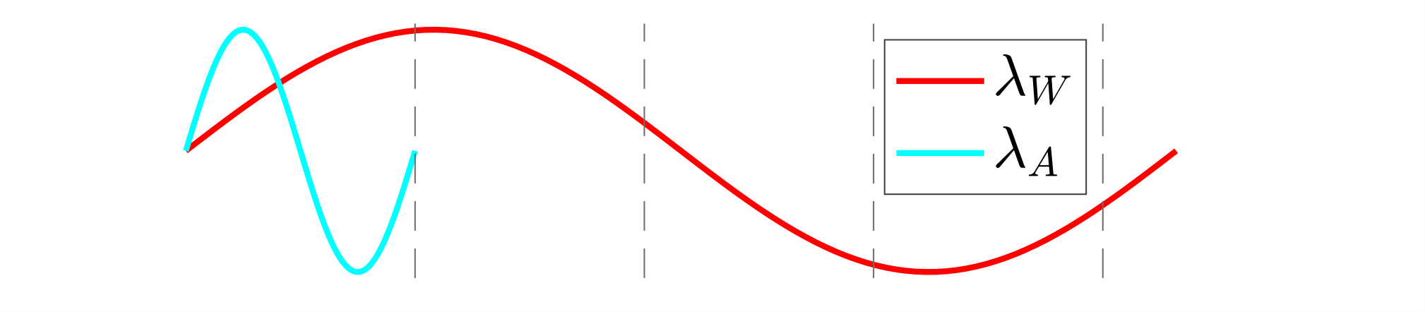
Figure 1: Wavelength of sound in air \((\lambda_A)\) vs in water \((\lambda_W)\) at \(20^\circ\) C for an arbitrary frequency.
It must be emphasized however, that inhomogeneities in the fluid can severely impact these results, as well as other factors such as pressure, temperature, dissipation, salinity... which must be taken into account for certain applications. A drastic example is given by the presence of air bubbles in water, where a \(1 \%\) volume fraction can reduce the (effective) sound speed by up to \(90 \%\), see \([2]\).
Presence of a boundary at normal incidence
We next showcase the differences that arise when a harmonic travelling wave solution is encountered with another acoustic medium. For simplicity, we only consider motion in one dimension so that, following the discussion above, the pressure field is of the form
\begin{equation}\label{linelastic setup}
p(x)= \begin{cases}
p_1=e^{-\mathrm{i} \omega x/c_{1}} + C_{1}e^{\mathrm{i} \omega x/c_1 } \quad \text{for} \quad x \leq 0\\
p_2=C_{2}e^{-\mathrm{i} \omega x/c_2} \hspace{2.35cm} \text{for} \quad x > 0
\end{cases}\tag{2}
\end{equation}
where the subscripts \(1\) and \(2\) are used to indicate the different quantities in each medium, see Figure 2 A. We must ensure that on the interface \(x=0\) we satisfy continuity of pressure \(p_1=p_2\), and normal velocity \(\frac{\mathrm{d} p_1}{\mathrm{d} x} = \frac{\rho_1}{\rho_2} \frac{\mathrm{d} p_2}{\mathrm{d} x}\) (via Euler's equations) which results in the reflected/transmitted amplitudes
\begin{equation}\label{complex amplitudes}
C_{1}= \frac{\mathcal{Q} - 1}{\mathcal{Q}+1} , \qquad
C_{2}= \frac{2 \mathcal{Q}}{\mathcal{Q}+1}, \qquad \text{where} \qquad \mathcal{Q} = \frac{\rho_2 c_{ 2}}{\rho_1 c_{1}}\tag{3}.
\end{equation}
Perhaps surprisingly, we observe that solutions \((3)\) are fully governed by \(\mathcal{Q}\), which represents the ratio of the acoustic impedance between the two media. In particular, we see that when \(\mathcal{Q}=1\), \(C_1 = 0\) i.e. there are no reflections and the two media are said to be impedance matched. On the contrary, for \(\mathcal{Q} \gg 1\) we obtain \(C_1 \rightarrow 1\) and \(C_2 \rightarrow 2\). Nevertheless, this limit is more insightful for the energy reflection/transmission coefficients, namely
\begin{equation}\label{ref/trans}
|R| = C_1^2, \qquad |T| = \mathcal{Q}^{-1} C_2^2=\frac{4 \mathcal{Q}}{(\mathcal{Q}+1)^2} \qquad \text{s.t.} \quad |R|+|T|=1\tag{4},
\end{equation}
which, given \((3)\) are easily obtained via energy conservation. We can now observe from \((4)\) that in fact \(|T| \rightarrow 0\) for \(\mathcal{Q} \gg 1\). In Figure \(2B\) we illustrate coefficients \((4)\) as a function of \(\mathcal{Q}\) with references values for various interfaces assuming medium \(1\) is a fluid (Air/Water) and medium \(2\) a solid (Steel/PVC). We observe that for air, transmission into the solid is negligible since \(\mathcal{Q} \gg 1\), whereas in water significant energy gets transmitted, even for stiff materials such as steel. This result has strong consequences in the modelling of UW acoustics, where the importance of fluid-structure interaction implies that in many cases the motion of neighbouring bodies must be taken into account, which ultimately results in coupled boundary conditions (see B is for Boundary Conditions) that are normally difficult to evaluate with analytical methods. In-air, however, transmission into solids can often be ignored and boundaries are considered (acoustically) rigid, resulting in major simplifications. For example, for air-solid interfaces the above simple problem can be formulated as a single acoustic medium with a sound-hard boundary condition, namely
\begin{equation}
\begin{cases}
p(x) =p_1=e^{-\mathrm{i} \omega x/c_{1}} + C_{1}e^{\mathrm{i} \omega x/c_1 } \quad \text{for} \quad x \leq 0\\
\frac{\mathrm{d} p}{\mathrm{d} x} = 0 \hspace{5.65cm} \text{on} \quad x = 0
\end{cases}\tag{5}
\end{equation}
which trivially gives \(C_1 = |R| = 1\) and we can observe that the induced error compared to the full solutions \((3)\), \((4)\) in the case of e.g. Steel/PVC, is negligible.

|
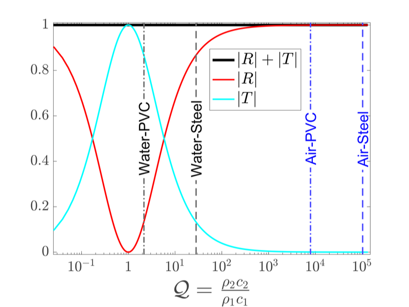
|
Figure 2: A) 1D reflection transmission problem set-up between two acoustic media. B) Reflection/Transmission coefficients (4) as a function of \(\mathcal{Q}\). The vertical lines indicate reference values for different fluid/solid interfaces. Click to enlarge.
Rapid human industrialisation has also led to an abundance of unwanted sources of noise in the oceans, caused by structures such as offshore wind farms, turbines, and large vessels which can greatly affect sensitive marine ecosystems (see e.g. \([3]\)).
This issue has raised much interest in the development of materials capable of attenuating UW sound. Due to their exciting characteristics, metamaterials/metasurfaces (see M is for Metamaterials) are promising candidates to tackle this problem. This topic is subject of current research and many designs continue to be proposed in the literature. Nevertheless, the vast majority of these are aimed to operate in-air and significant work remains to be done in the UW regime, especially in oceans which can be very hostile environments.
In the MWM group, we are interested in the mathematical modelling of the underlying physical phenomena in acoustic metamaterials. One of the unavoidable mechanisms present in these structures is that of visco-thermal dissipation, which is the main topic of study in my PhD. Through maths, we hope our work can give new insights that are ultimately incorporated into material manufacturing. One of our studies on boundary layer effects in acoustic propagation of narrow slits in both air and water is given in \([4]\).
E. Garcia-Neefjes
[1] Lurton, X. (2002) An introduction to underwater acoustics: principles and applications. London: Springer Science & Business Media.
[2] Gibson, F. W. (1970), "Measurement of the effect of air bubbles on the speed of sound in water." The journal of the Acoustical Society of America, 48.5B, 1195-1197.
[3] Rolland, R. M., Parks, S. E., Hunt, K. E., Castellote, M., Corkeron, P. J., Nowacek, D. P., Wasser, S. K. and Kraus, S. D. (2012) "Evidence that ship noise increases stress in right whales." Proceedings of the Royal Society B: Biological Sciences 279.1737, 2363-2368.
[4] Cotterill, P. A., Nigro, D., Abrahams, I. D., Garcia-Neefjes, E. and Parnell, W. J. (2018) "Thermo-viscous damping of acoustic waves in narrow channels: A comparison of effects in air and water." The Journal of the Acoustical Society of America, 144(6), 3421-3436.
V is for Vector Calculus
Vector calculus provides the concepts and notation needed to describe many physical laws and processes as concise conservation equations, which is one of the reasons for its ubiquity as a key component of first-year undergraduate mathematics and natural science courses [1]. In simplistic terms, the secondary school topics of vectors and calculus are combined, and most students quickly grasp the basic ideas involved in the definition of a partial derivative, but there are other mathematical subtleties which can be easily overlooked.
To illustrate how a physical conservation process may be expressed as a partial differential equation, via vector calculus, we can consider the following general statement:
\begin{equation*}
\left(\begin{array}{c}
\textrm{Rate of}\\
\textrm{change of}\\
\textrm{quantity}\\
\textrm{in system}
\end{array}
\right)=
\left(
\begin{array}{c}
\textrm{Rate of}\\
\textrm{quantity}\\
\textrm{entering}\\
\textrm{system}
\end{array}
\right)
-
\left(
\begin{array}{c}
\textrm{Rate of}\\
\textrm{quantity}\\
\textrm{leaving}\\
\textrm{system}
\end{array}
\right)
+
\left(
\begin{array}{c}
\textrm{Rate of}\\
\textrm{internal}\\
\textrm{growth of}\\
\textrm{quantity}
\end{array}
\right).
\end{equation*}
Here the quantity could be practically anything being modelled, from oxygen in a building, money in a bank account, population of worms in a garden etc., while the system refers to some relevant region or domain with specified boundaries.
If we denote the overall amount of the quantity in the system as \(V\), the net flux (i.e. amount passing through the boundaries per unit time) of the quantity into the system as \(Q\), and the internal growth rate within the system as \(R\) (possibly negative for a decaying quantity), then the general statement (in words) may be expressed by the straightforward equation
\begin{equation*}
\frac{dV}{dt} = Q + R.
\end{equation*}
To incorporate spatial variation, we must unpack \(V\), \(Q\), and \(R\) using scalar and vector fields to make the notation more local in a continuum context. Suppose we denote the system under consideration as \(\omega\) (often a 2D or 3D geometrical region in physical problems), and the system’s boundaries as \(\partial\omega\) (often a corresponding 1D curve or a 2D surface). Then suppose we denote the local density of the quantity at a point \({\bf x}\) within \(\omega\) and at a time \(t\) as \(\phi({\bf x},t)\), and the flux density (i.e. flux per unit boundary area) of the quantity at a point \({\bf x}\) on \(\partial\omega\) and time \(t\) as \({\bf f}({\bf x},t)\), and the internal growth rate of the quantity per unit volume at a point \({\bf x}\) within \(\omega\) and time \(t\) as \(r({\bf x},t)\). Then we can recast the conservation equation in integral form:
\begin{equation*}
\frac{d}{dt}\int_{\omega} \phi \ dV = - \int_{\partial\omega} {\bf{f}} \cdot {\bf{n}} \ dS + \int_{\omega} r \ dV,
\end{equation*}
where \({\bf n}({\bf x},t)\) is the outward normal vector at each point \({\bf x}\) on \(\partial\omega\). Here the negative term on the right-hand side is due to the convention of taking outward normal, such that a positive \({\bf{f}} \cdot {\bf{n}}\) corresponds to an overall outflow, i.e. a reduction in the total amount within the system.
By applying key theorems from vector calculus, the integral form of the conservation equation can be further condensed to yield a partial differential equation that encapsulates the physical process at a point-wise level. For equations of the form above, the first step is to use the divergence theorem to replace the surface integral with a volume integral, and then combine all three terms as a single volume integral:
\begin{equation*}
\int_\omega \left[ \frac{\partial {\phi}}{\partial t} + \nabla \cdot {\bf f} - r \right] dV = 0\,.
\end{equation*}
Here an assumption has been made that the boundaries of \(\omega\) are fixed in time – if this is not the case then we apply the Reynolds transport theorem [2], with additional terms resulting.
The next step is to exploit the fact that this equality must hold for any \(\omega\), or in other words we can replace the original system \(\omega\) with an arbitrary subregion, and derive the same equation for that subregion. Hence, due to the continuity of the scalar and vector fields (for a physical process), the integrand must be identically zero everywhere, which gives us the partial differential equation
\begin{equation*}
\frac{\partial {\phi}}{\partial t} + \nabla \cdot {\bf f} = r.
\end{equation*}
The above is a general derivation illustrating how the concepts and notation of vector calculus provide the platform to express physical processes in mathematical form. Some particular examples of well-known equations which follow directly are the heat equation, and the momentum and mass equations for an inviscid fluid.
N. F. Morrison
[1] Riley, K., Hobson, M. & Bence, S., 2002. Mathematical Methods for Physics and Engineering: A Comprehensive Guide. 2nd ed. Cambridge: Cambridge University Press.
[2] Owens, R. G. & Phillips, T. N., 2002. Computational Rheology. 1st ed. London: Imperial College Press.
[2] Owens, R. G. & Phillips, T. N., 2002. Computational Rheology. 1st ed. London: Imperial College Press.
W is for wiener-Hopf
 *Wiener and Hopf
The Wiener-Hopf Technique
An important part of our work in the mathematical study of waves relies heavily on deep results in Complex analysis. In particular, we have a strong expertise in the so-called Wiener-Hopf technique. This technique, first developed to tackle integral equations [1], has been adapted by Copson [2] and Jones [3] to tackle boundary value problems directly. It is very powerful and has been really successful for analytically solving canonical problems for a broad range of applications: acoustics, electromagnetism, elasticity, water-waves, Stokes flows, heat equation, etc. It is traditionally associated to two-dimensional problems and involves functions of one complex variable. The archetypical example of the power of this technique is the resolution of the Sommerfeld half-plane diffraction problem [4]. A brief historical perspective is given by Lawrie & Abrahams in [5].
The essence of the technique consists in using the Fourier (or Laplace) transform to pass from a Boundary value problem (PDE + boundary conditions) in the physical space into a functional equation in the complex Fourier space (\(\alpha\) say). Such a functional equation normally takes the form:
$$\begin{equation}K(\alpha)\Phi_+(\alpha) = \Phi_-(\alpha) +F(\alpha),\tag{1} \label{eq:functional}\end{equation}$$
where \(K\) is a known (most often algebraic) function traditionally called the kernel and \(F\) is a known forcing that usually only contains simple poles. In our context, the two unknown functions of the problem, \(\Phi_+\) and \(\Phi_-\), are the transforms of the unknown wave field. It is however, normally known that \(\Phi_+\) is analytic in the upper-half \(\alpha\) complex plane, while \(\Phi_-\) is analytic in the lower-half plane. The kernel \(K\) is analytic on the intersection between these two half planes.
Often the kernel has a complicated singularity structure, involving branch points, poles, etc. One of the key aspects of the method is to be able to write \(K(\alpha)=K_+(\alpha) K_-(\alpha)\), where \(K_+\) is analytic in the upper half \(\alpha\) complex plane and \(K_-\) is analytic in the lower half plane. This is called a factorisation of the kernel.
Another step of a similar nature can be done involving the concept of a sum-split. For example, \(G(\alpha)=G_+(\alpha)+G_-(\alpha)\) where \(G_+\) is analytic in the upper half \(\alpha\) complex plane and \(G_-\) is analytic in the lower half plane. We finish with the use of Liouville's theorem after noting the boundedness of the individual terms. The end result gives us an exact expression for \(\Phi_+\) and \(\Phi_-\).
The physical field can be recovered directly via inverse Fourier transform, i.e. a typical complex contour integral. The deformation of contour integration is allowed under certain hypotheses, and choosing the right deformation for optimal evaluation is also a very interesting research topic that we are involved in.
The application of the Wiener-Hopf technique necessitates a very good understanding of functions of one complex variable and their possible features (poles, branch points, branch cuts, etc). Visualising complex functions is not necessarily straightforward. If one is interested in the location at type of singularities of a function, a simple visualisation tool, called phase portrait can be used (see P is for Phase Portrait). On such plots, branch cuts are colour discontinuities, and poles and zeroes can also be easily distinguished. Figure 1 is a phase plot visualisation of the factorisation of the kernel, \(K(\alpha)=\sqrt{k^2-\alpha^2}\), which arises for the Sommerfeld half-plane diffraction problem (among others).
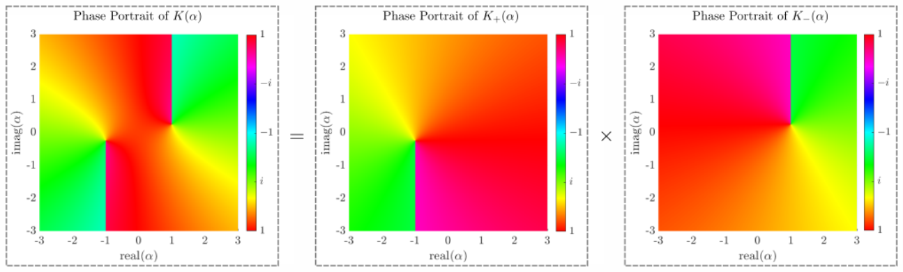
Figure 1: Phase portraits showing the factorisation of the kernel \(K(\alpha)=\sqrt{k^2-\alpha^2}\).
Discrete Wiener-Hopf Technique
For periodic scattering problems such as the semi-infinite array, a variation of the Wiener-Hopf technique is still a very powerful tool. This variation is known as the discrete Wiener-Hopf technique [6,7]. The procedure is mostly unchanged but does have a few notable differences. One of these key differences is the transform used to produce the functional equation, which is the \(Z\)-transform instead of Fourier or Laplace. The resulting functional equation takes the same form as \((\ref{eq:functional})\), but this time, the analytic regions of the unknown functions, \(\Phi_+\) and \(\Phi_-\), are inside and outside the unit circle of the \(z\) complex plane given by \(|z|=1\).
In the semi-infinite array scattering problem, the kernel \(K(z)\) is an infinite sum of first kind Hankel functions at zeroth order,
$$\begin{equation}K(z)=H^{(1)}_0(ka)+\sum_{n=1}^\infty (z^n+z^{-n})H^{(1)}_0(ksn), \label{eq:DWHkernel}\end{equation}$$
which only converges on the unit circle \(|z|=1\). There are various methods that can be employed to accelerate the convergence of \((\ref{eq:DWHkernel})\) and alternative formulae that analytically continue it further than the unit circle. We can also approximate the kernel as a rational function using highly effective algorithms, such as "AAA" of Chebfun, which results in a highly accurate approximation that makes the kernel factorisation step of the Wiener-Hopf technique trivial. Figure 2 displays the approximation and factorisation of the kernel \((\ref{eq:DWHkernel})\).
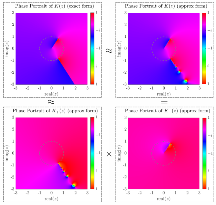
Figure 2: Phase portraits showing the discrete Wiener-Hopf kernel with its rational approximation and the approximate factors. Here the grey dashed circle is the unit circle \(|z|=1\).
The Matrix Wiener-Hopf Technique
For "simple" diffraction problems involving one infinite scatterer, both the kernel, the unknowns and the forcing in \((\ref{eq:functional})\) are scalar functions. However when multiple scatterers are present, or when scatterers have finite length, the kernel becomes a matrix and the forcing and unknowns are vectors. In this situation, the factorisation (though possible in principle) becomes much more complicated to do in practice and remains an ongoing theoretical challenge [8,9].
For "simple" diffraction problems involving one infinite scatterer, both the kernel, the unknowns and the forcing in \((\ref{eq:functional})\) are scalar functions. However when multiple scatterers are present, or when scatterers have finite length, the kernel becomes a matrix and the forcing and unknowns are vectors. In this situation, the factorisation (though possible in principle) becomes much more complicated to do in practice and remains an ongoing theoretical challenge [8,9].
Towards a multidimensional Wiener-Hopf Technique?
Generalising the Wiener-Hopf technique to three-dimensional physical problems would be a tremendous achievement in diffraction theory. However, this is far from being straight-forward. One of the reasons is that it involves functions that depend on more than one complex variable, such as functions on \(\mathbb{C}^2\) or on \(\mathbb{C}^3\) for example, that are 4 and 6 dimensional spaces respectively.
For three-dimensional problems, such as the quarter-plane problem (the direct 3D extension of the Sommerfeld problem), boundary value problems can also be recast as a functional equation of the form \((\ref{eq:functional})\), but this time, the functions involved are functions of several complex variables, and their domain of analyticity can be written in terms of products of upper-half and lower-half complex planes.
In this situation, the singularities of the functions (very important for the Wiener-Hopf technique as we have seen above) are not isolated points anymore, but become more complicated geometrical objects. In \(\mathbb{C}^2\) for example, a pole or a branch are unbounded objects of real dimension 2 embedded in dimension 4.
We are currently doing a lot of work on this topic [10-14]. In fact, a few lectures were given jointly by Raphael Assier and his collaborator Andrey Shanin on these specific topics as part of a 2019 Newton Institute programme. These are aimed at applied mathematicians, familiar with one-dimensional complex analysis, but keen to know more about the challenges of multidimensional complex analysis. Here are the links:
Lecture 1 | Lecture 2 | Lecture 3 | Lecture 4 | Lecture 5
If you don't like the chalk and talk approach, a three-lecture series condensing our recent results in applied multidimensional analysis has been given in 2021 by Raphael Assier as part of a American Mathematical Society Mathematical Research Community (MRC) hosted by Harvard University:
MRC Lecture 1 | MRC Lecture 2 | MRC Lecture 3 |
M. Nethercote, R. Assier
[1] Wiener, N., Hopf, E. (1931) Über eine klasse singulärer integralgleichungen, Sitzungsberichte Preuss. Akad. Wissenschaften, Phys. Klasse (in German), 31, 696–706.
[2] Copson, E. T. (1946) On an integral equation arising in the theory of diffraction, Q. J. Math., 17(1), 19-34.
[3] Jones D. S. (1952) A simplifying technique in the solution of a class of diffraction problems, Q. J. Math., 3(1), 189-196.
[4] Noble, B. (1958) Methods based on the Wiener-Hopf Technique for the solution of partial differential equations (1988 reprint), New York: Chelsea Publishing Company.
[5] Lawrie, J. B., Abrahams, I. D. (2007) A brief historical perspective of the Wiener-Hopf technique, J. Eng. Math., 59, 351-358.
[6] Hills, N. L., Karp, S. N. (1965) Semi-Infinite Diffraction Gratings-I, Comm. Pure App. Math., 18, 203-233.
[7] Linton, C. M., Martin, P. A. (2004) Semi-Infinite Arrays of Isotropic Point Scatterers. A Unified Approach, SIAM J. Appl. Math., 64(3), 1035-1056.
[8] Abrahams, I. D., Wickham, G. R. (1988) On the scattering of sound by two semi-infinite parallel staggered plates - I. Explicit matrix Wiener-Hopf factorization, Proc. R. Soc. Lond. A, 420, 131-156.
[9] Kisil, A., Abrahams, I. D., Mishuris, G., Rogosin, S. (2021) The Wiener-Hopf Technique, its Generalisations and Applications: Constructive and Approximate Methods, arXiv:2107.06088 [math.CA]
[10] Assier, R. C., Shanin, A. V. (2019) Diffraction by a quarter-plane. Analytical continuation of spectral functions, Q. J. Mech. Appl. Math., 72(1), 51-86.
[11] Assier, R. C., Abrahams, I. D. (2020) On the asymptotic properties of a canonical diffraction integral, Proc. R. Soc. A, 476, 20200150.
[12] Assier, R. C., Shanin, A. V. (2021) Analytical continuation of two-dimensional wave fields, Proc. R. Soc. A, 477, 20200681.
[13] Assier, R. C., Abrahams, I. D. (2021) A Surprising Observation in the Quarter-Plane Diffraction Problem, SIAM J. Appl. Math., 81(1), 60-90.
[14] Assier, R. C., Shanin, A. V. (2021) Vertex Green's Functions of a Quarter-Plane: Links Between the Functional Equation, Additive Crossing and Lamé Functions, Q. J. Mech. Appl. Math., hbab004.
*We do not own the copyright to these images of Wiener and Hopf, however we believe that they are in the public domain. If you believe that you own the rights to them and wish us to remove them, or add a credit please contact us
X is for X-Ray Computed Tomography
If you have ever broken a bone, it is likely you were sent for ‘an X-ray’ to assess the damage. These scans are actually called X-ray radiographs, which show the density of features within the scanned area. X-ray radiography is familiar in a medical context but is also common in engineering as a method of non-destructive testing (NDT) to identify weld defects, casting imperfections, corrosion, pitting and other issues. The contrast in an X-ray radiograph is due to differences in attenuation along different paths from the source, through the sample or patient, to the detector. Attenuation is due to both scattering and absorption events; with the latter process typically dominating. Since X-ray absorption is strongly dependant on the material density, radiographs readily reveal the presence of high/low density features, such as cracks within a bone or weld; even where the cracking is entirely internal [1,2].
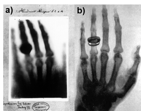
Figure 1 - Early X-ray radiographs: a) print of the first ever medical X-ray image, conducted by Wilhelm Röntgen on the hand of his wife, Anna Bertha, in December 1895. Bertha was quoted as saying “I have seen my death!” on seeing her skeleton captured in the image. Röntgen later took a far clearer image of anatomist Albert von Kölliker (b), live in front of a lecture audience. Public domain, via Wikimedia Commons
The attenuation of X-rays is described by the Beer-Lambert law, which states that at a depth, \(x\), into a material, the intensity, \(I_x\), is given by \(I=I_0 e^{-\mu x}\), where \(I_0\) is the intensity of the incident beam and \(\mu\) is the attenuation coefficient of the material. Where the scanned material consists of multiple phases, there will be different values of µ at different points, with the Beer-Lambert law taking the form \(I=I_0e^{-\sum(\mu_1 x_1 + \mu_2 x_2 +...)}\). The contrast of each pixel in an X-ray radiograph is therefore a measure of the total \(\mu\) along the corresponding source-sample-detector path; it cannot discern the position of absorbing features along that path or separate contributions from multiple attenuating features [1].
This information can be obtained via X-Ray computed tomography (CT) however, where the information from multiple radiographs is combined and reconstructed into a 3D density (strictly \(\mu\)) map of the sample. To conduct an X-ray CT scan, radiographs of the target are first collected from multiple angles, achieved via rotation of the sample, or the source and detector. For an accurate reconstruction, a large angular coverage of radiographs (or projections) is required, at a fine (<1°) step size. Typically, thousands of projections are collected, covering the full 360° [1]. CT scan times range from minutes for weakly attenuating materials (e.g. medical cases) to hours or even days for engineering materials. Reconstruction of the radiographs is achieved through a process known as back projection, as depicted in Figure 2. Essentially, for each pixel in each radiograph, the implied value of \(\mu\) is spread evenly back along its corresponding source-detector path. As further projections are added, a concentration in the computed value of \(\mu\) arises at points corresponding to attenuating features within the sample. With enough projections, a 3D reconstruction which accurately represents the original sample can be obtained [2]. Alternatively, iterative reconstruction algorithms can be used. These algorithms work by guessing the structure of the sample, simulating the X-ray attenuation at different angles, and comparing with the experimentally obtained projections; the solution is then iterated until the required level of agreement is reached [1].
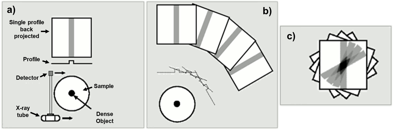
Figure 2 - Depiction of acquisition and back-projection of X-ray radiographs: a) acquisition of a single radiograph using a moving source and detector (for wide-angle sources, the entire radiograph can be collected at a single position); b) acquisition of several radiographs from different angular positions; c) back-projection of the collected radiographs, leading to an accumulation of µ at the point of the dense object. In practice, the projections are filtered prior to this, to avoid the point-spread blur around the feature seen here (known as filtered back-projection). Image credit: Kieran Maher, public domain, adapted from https://commons.wikimedia.org/wiki/File:NM19_3.png
Modern X-ray detectors typically have 1000+ pixels along each dimension, meaning that for samples sizes in the order of millimetres, sub-micron resolutions can be achieved. As such, CT can be used to perform accurate measurements of various internal features, such as cracks, voids, or inclusions and often this analysis can be automated. Sample sizes must be tailored, according to how strongly the material attenuates X-rays, but CT is a versatile technique, which can be applied to virtually all material types, including metallics, ceramics and polymers as well as biological and geological samples. As it is a non-destructive technique, it is increasingly being used to guide multi-technique, correlative studies towards regions of interest [3]. Various in-situ experiments, most commonly tension/compression or high-temperature studies, can be combined with CT imaging, allowing degradation mechanisms to be observed directly. At synchrotron facilities, where x-ray sources are >1000x brighter than lab sources, the possibility arises to conduct ultra-fast time-lapse studies, or to resolve fine details in otherwise opaque materials [2,4].

Figure 3 - Volume rendering of an X-Ray CT scan showing the skull of a Pawpawsaurus. The scan allowed the researchers to infer new information about the dinosaur’s internal vasculature and nasal cavity airflow, without damage to the specimen. Image CC BY 4.0, https://creativecommons.org/licenses/by/4.0/ from reference [5].
M. Curd
[1] Smith, S. W., (1997) The Scientist and Engineer’s Guide to Digital Signal Processing, Sci. Eng. Guid. to Digit. Signal Process. 423–450. doi:10.1016/B978-0-7506-7444-7/50062-5.
[2] Salvo, L., Cloetens, P., Maire, E.,Zabler, S., Blandin, J. J., Buffière, J. Y., Ludwig, W., Boller, E., Bellet, D., Josserond, C. (2003) X-ray micro-tomography an attractive characterisation technique in materials science, Nucl. Instruments Methods Phys. Res. Sect. B Beam Interact. with Mater. Atoms. 200 273–286. doi:10.1016/S0168-583X(02)01689-0.
[3] Burnett, T. L., McDonald, S., A., Gholinia, A., Geurts, R., Janus, M., Slater, T., Haigh, S. J., Ornek, C., Almuaili, F., Engelberg, G.E. Thompson, Withers, P. J. (2014) Correlative tomography., Sci. Rep. 4, 4711. doi:10.1038/srep04711.
[4] Maire E., Withers P. J. (2014) Quantitative X-ray tomography, Int. Mater. Rev. 59, 1–43. doi:10.1179/1743280413Y.0000000023.
[5] Paulina-Carabajal, A., Lee, Y. N., Jacobs, L .L. (2016) Endocranial morphology of the primitive nodosaurid dinosaur Pawpawsaurus campbelli from the Early Cretaceous of North America, PLoS One. 11,1–22. doi:10.1371/journal.pone.0150845.
Y is for young
|
Thomas Young (1773-1829) was a physician and scientist who contributed a great deal to our understanding of waves and materials, as well as a host of other phenomena. Often described as a polymath, Young’s areas of study and expertise were so varied, that he has been dubbed “The last man who knew everything” [1].
The eldest of 10 children belonging to a Quaker family in Somerset, Young displayed a prodigious intelligence from a young age. A reader by the age of two, he became proficient in Latin, classical Greek and several modern languages as a young man. Young had an interest in mathematics and physics, but undertook the study of medicine. He studied first at St Bartholomew’s hospital, where he showed considerable talent for anatomy, then at Edinburgh, and Göttingen in Germany, finally matriculating at Cambridge, where he earned the nickname “Phænomenon Young” for his encyclopaedic knowledge and abilities [2]. |
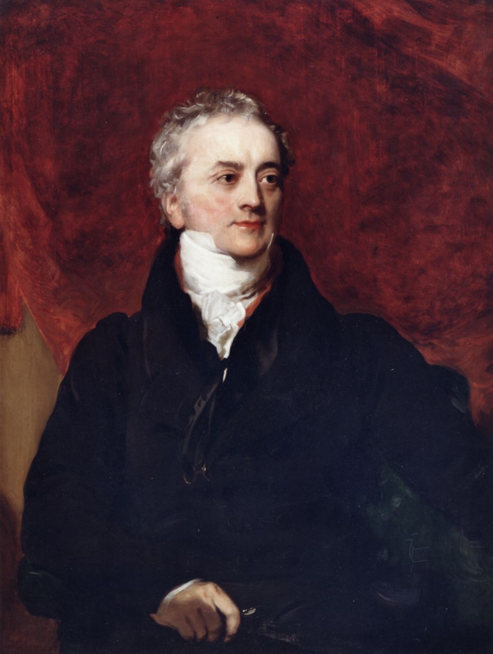
Portrait of Thomas Young, Henry Perronet Briggs. Public domain, via Wikimedia Commons.
|
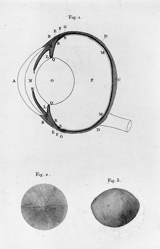
Anatomy of the Human Eye by Thomas Young. Image from Science Museum Group CC BY 4.0, https://creativecommons.org/licenses/by/4.0, via Wikimedia Commons.
|
Young’s talents were recognised early: he was elected a fellow of the Royal Society in 1794, at just 21, and appointed its Foreign Secretary in 1802. Young held a professorship at the Royal Institution from 1801, but resigned from it in 1803 to focus on his medical career [3]. While best known in modern times for his contributions to physics, Thomas Young’s expertise extended much further. His work in decoding the two Egyptian scripts on the Rosetta Stone paved the way for its later full translation [1]. Young was an authority on linguistics, and coined the term Indo-European in 1813. In anatomy, he discovered astigmatism, elucidated the mechanism for focus in the human eye, and suggested three-colour vision. In addition to all this, Young wrote several contributions to the Encyclopaedia Britannica, and was employed as an adviser to the Admiralty on shipbuilding [4].
Young’s most famous scientific contributions are in the disciplines of waves and materials. We will focus on two developments: his identification of the material property now known as Young’s Modulus, and his contribution to the wave theory of light with his famous Double Slit experiment. |
Young’s Modulus
Thomas Young lived during the Industrial Revolution, an age of engineering when an understanding of material properties, particularly tensile strength, was of extreme importance. Young’s lecture “On Passive Strength and Friction” describes the relationship between stress and strain (see E for Elasticity, above), and introduces the concept of elastic modulus [5]. It should be noted, however, that Young’s writing lacked clarity and was often obscure and lacking in figures, and as a result was not popular with his contemporaries. For example, he described the elasticity of a substance as …a column of the same substance, capable of producing a pressure on its base which is to the weight causing a certain degree of compression, as the length of the substance is to the diminution of its length.
We owe our modern interpretation of Young’s modulus as the ratio of stress to strain:
\(E=\frac{\sigma}{\epsilon}\),
where \(\sigma\) is the stress, or applied force per unit area, and \(\epsilon\) is the strain, or extension per unit length, to Claude-Louis Navier [4].
|
Wave Theory
Young’s explorations with light stemmed from his interest in music and acoustics, and early work on wave interference [2]. In his “Outlines of Experiments and Inquiries Respecting Sound and Light”, Young begins with various explorations into the nature of sound and acoustics, and later addresses the “analogy between light and Sound”. For instance, he compared the recurrence of colours in “Newton’s rings” (patterns of coloured rings that form between curved glass surfaces), and its relation to the thickness of the glass, to the production of the same tone in organ pipes whose lengths are integer multiples. |

Newton's Rings between 2 plano convex lenses. Credit: Ulfbastel, public domain, via Wikimedia Commons
|
Young’s famous “Double Slit” experiment further supported a wave model of light. Young noted “fringes of colours are produced by the interference of two portions of light” [6]. These fringes are the diffraction pattern we see when light passes through two closely spaced slits and is projected onto a distant screen – as in the diagram below. Pattern of constructive interference result in the bright spots. Young observed that constructive interference occurs where the difference in path length from the two slits to a point on the screen is equal to an integral number of wavelengths, and noted that a particle model of light could not account for this phenomenon.
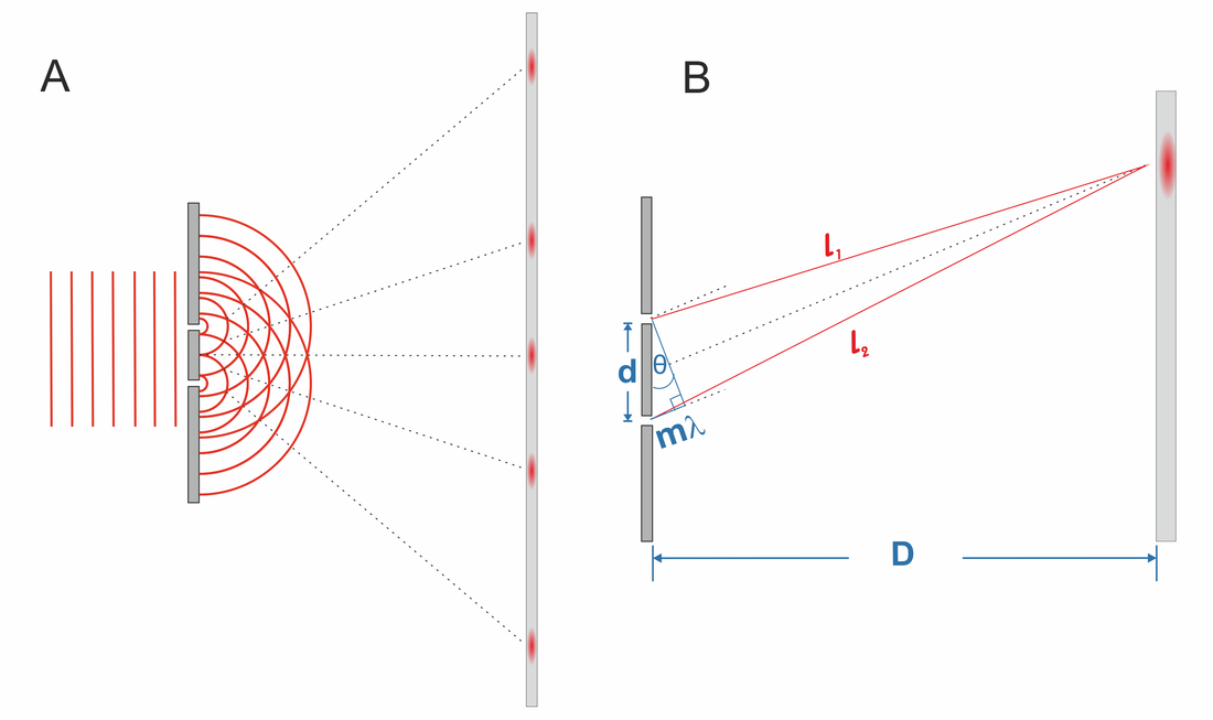
A: Schematic diagram of the Double Slit experiment. B: Constructive interference occurs where the difference in path lengths \(l_1\) and \(l_2\) is equal to \(m\lambda=dsin\theta\), where \(d\) is the distance between the two slits (must be much smaller than \(D\), the distance from the slits to the "screen"), the angle \(\theta\) between the path and a line from the slits to the screen is nearly the same for each path and \(m=0, 1, -1, 2, -2, . . .\).
To put Young’s discoveries in context, the dominant theory of light in Britain at the time was Newton’s corpuscular (particle) model, and resistance to the wave models which were gaining popularity in Europe was widespread. Vociferous criticism of his work from proponents of particle theory, combined with its inability to account for the polarization of light (observed by Malus in 1807), discouraged Young’s pursuit of the wave model. Later, though, his theory gained the support of other scientists including Fresnel and Ampère and Young suggested (along with others) that if light travelled as a transverse wave, rather than longitudinal, the phenomenon of polarization would fit with a wave model [2].
[1] Robinson, A. (2006). Thomas Young: The Man Who Knew Everything, History Today, 56, 53-57
[2] Pesic, P. (2013). Thomas Young’s Musical Optics: Translating Sound into Light. Osiris, 28(1), 15-39. doi:10.1086/671361
[3] Altenbach, H. (2020). Young, Thomas. In H. Altenbach & A. Öchsner (Eds.), Encyclopedia of Continuum Mechanics (pp. 2789-2790). Berlin, Heidelberg: Springer Berlin Heidelberg.
[4] Brock, R. (2020) Stories from physics: properties of matter, (pp. 4-6) Bristol: Institute of Physics.
[5] Hondros, E. D. (2005). Dr. Thomas Young—Natural philosopher. Journal of Materials Science, 40(9), 2119-2123. doi:10.1007/s10853-005-1889-8
[6] Young, T. (1804). The Bakerian Lecture: Experiments and Calculations Relative to Physical Optics. Philosophical Transactions of the Royal Society of London, 94, 1-16.
Z is for Acoustic Impedance!
Now, you may be wondering how we have ended up back at 'A', for the letter 'Z'. Well, a bit of artistic licence has been taken and for 'Z' the acoustic impedance, which is commonly denoted by \(Z\), will be discussed.
Acoustic waves propagating in one direction can be described by an oscillating scalar pressure, \(p\), and a one dimensional velocity, \(v\), which are considered to be periodic in space and time:
\begin{equation}
p(x,t) = \tilde{p}\exp\{i(\omega t - kx)\}, \quad v(x,t) = \tilde{v}\exp\{i(\omega t - kx)\}\tag{1},
\end{equation}
where \(\omega\) is the frequency, \(k\) is the wavenumber, and \(\tilde{p}\) and \(\tilde{v}\) are the amplitudes of the pressure and velocity respectively. The acoustic impedance is a material property which links the pressure and velocity amplitudes for a given material, and can be calculated for any homogeneous material as the product of density and speed of sound:
\begin{equation}
Z = \frac{\tilde{p}}{\tilde{v}} = \rho_0 c_0\tag{2},
\end{equation}
where \(\rho_0\) and \(c_0\) are the density and speed of sound of a given material respectively. Table 1 shows the acoustic impedance for a few different materials.
Table 1. Table of impedance for various materials, taken from [1] and [2]
|
The acoustic impedance becomes important when considering the transmission of acoustic waves from one medium to another, as the difference in impedance in two materials can lead to reflection as well as refraction (briefly discussed in D for Diffraction and U for Underwater Acoustics, above). Figure 1 shows two phases of material \(\Omega_1\) and \(\Omega_2\) with acoustic impedance \(Z_1\) and \(Z_2\) respectively. The incoming wave is partially reflected at the interface, denoted by the blue dotted line, and partially transmitted, denoted by the purple line. The transmitted wave experiences refraction, meaning that the angle of propagation relative to the interface changes in \(\Omega_2\). The reflection coefficient, \(R\) can be given in term of \(Z_1\) and \(Z_2\) [1]:
\begin{equation}
R = \Big(\frac{Z_1 - Z_2}{Z_1 + Z_2}\Big)^2\tag{3},
\end{equation}
where a reflection coefficient of 0 means that none of the incoming energy is reflected, and a reflection coefficient of 1 means that all the energy is reflected. Similarly, the transmission coefficient is given by \(T = 1 - R\). By considering the impedance in Table 1, it can be seen that a sound travelling between air and a harder material, even a liquid such as water, has a large reflection coefficient, which is why if you put your head underwater, external noises become difficult to hear.
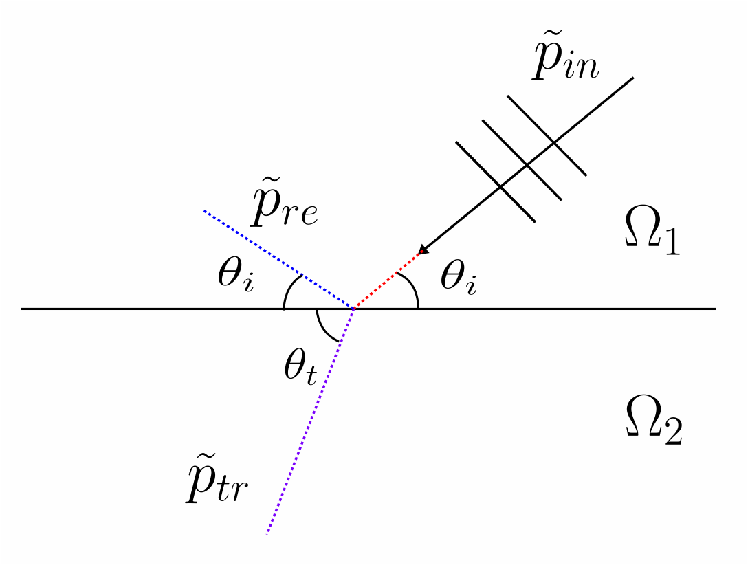
Figure 1: Diagram showing transmittance and reflection of a wave at the interface between two material phases, \(\Omega_1\) and \(\Omega_2\).
An application where knowledge about acoustic impedance is essential is in medical ultrasound. An ultrasound device generates an image by sending out high frequency acoustic waves and constructing an image from the reflected wave field [2]. As the ultrasound wave passes through the different phases of the body, there are changes of impedance and therefore reflection of the ultrasound waves. The waves will be reflected at different rates at different points in the body, illustrated by the impedance of bone and muscle in Table 1, and therefore by understanding these differences, images can be constructed of parts of the inside of the body.
Another problem where a knowledge of the acoustic impedance is important is in the modelling of sound absorbing materials, such as porous materials. These materials can be used to line a space where sound is propagating, instead of a rigid wall, in order to absorb acoustic energy, through visco-thermal losses, rather than reflecting the energy. Although these materials are not homogeneous, the effective properties can be found through homogenisation techniques, and an effective impedance can be found, which in general is frequency dependent [3]. For sound absorbing materials, the impedance is given by a complex number, where the real part gives information on how an incoming wave will be reflected/transmitted, and the imaginary part allows us to find how the transmitted wave is absorbed by the porous material.
Another problem where a knowledge of the acoustic impedance is important is in the modelling of sound absorbing materials, such as porous materials. These materials can be used to line a space where sound is propagating, instead of a rigid wall, in order to absorb acoustic energy, through visco-thermal losses, rather than reflecting the energy. Although these materials are not homogeneous, the effective properties can be found through homogenisation techniques, and an effective impedance can be found, which in general is frequency dependent [3]. For sound absorbing materials, the impedance is given by a complex number, where the real part gives information on how an incoming wave will be reflected/transmitted, and the imaginary part allows us to find how the transmitted wave is absorbed by the porous material.
T. White
[1] Dertien, E. and Regtien, P. (2018). Sensors for Mechatronics, 2nd Edn. Amsterdam: Elsevier.
[2] Chan, V. and Perlas, A. (2011). 'Basics of ultrasound imaging' in Atlas of ultrasound-guided procedures in interventional pain management, Narouze, S. N. Ed., New York: Springer, 13-19.
[3] Champoux, Y. and Allard, J. F. (1991). Dynamic tortuosity and bulk modulus in air‐saturated porous media, Journal of applied physics, 70(4),1975-1979.