MATHEMATICS OF WAVES AND MATERIALS
  • Home
  • People
  • Research
    • Research interests
    • Publications
    • Grants
    • External Conferences
    • Research Talks
    • Opportunities
  • Events
  • Group meetings
    • Online Seminars
  • Industry
    • Industrial Collaborations
    • Thales
    • Dyson
  • Engagement
    • Our Research Explained
    • Meet a Mathematician
    • Virtual Postcards
    • Smarter Materials for Greener Devices
    • Learning Resources >
      • Primary Learning Resources >
        • Make a Kazoo!
        • Noisy Balloons!
        • Hundreds and Thousands
      • Secondary Learning Resources >
        • The Anatomy of a Wave
        • Resonance and Standing Waves
        • The Science of Musical Instruments
        • The Science of Balloons Part 1
        • The Science of Balloons Part 2
        • Draw Curves with Straight Lines
        • Sci-Fi Slinky Sounds
        • Resonant Rings
        • Floating Slinky
        • Slow Waves
        • Unmixing
      • Slinky Science
    • Schools and Colleges
    • Public Events
    • Get in touch
    • Social Media
    • Community Festival Waves and Sound
  • A to Z
  • Contact
  • Blog

Illustrating the Research

6/3/2020

0 Comments

 
We worked with Illustrator John Cooper to create a short video about metamaterials for noise reduction.
Picture
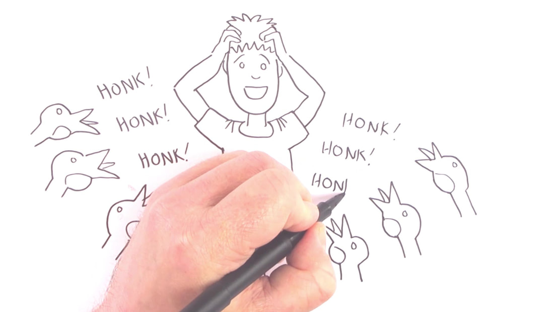
Still image from the video. Credit: John Cooper.
One of the things researchers often wrestle with is creating clear and succinct explanations of their research for the non-specialist.  It can be extremely helpful to work with others; such as illustrators, teachers and performers, to eliminate jargon and create meaningful outputs that showcase the research.

When we wanted to make a short video about the design of metamaterials for noise reduction devices, we turned to illustrator and comedian John Cooper.

John has worked on projects for the University of Manchester before, creating work for the University’s School Governor Initiative and for the Children’s University of Manchester.  His humorous style lends clarity and informality to a topic.

We started from a blog post about the piece of research in question.  John used it to sketch out an initial storyboard proposal featuring noisy geese!  We then put together an initial script, from which John created a slideshow storyboard.
Picture
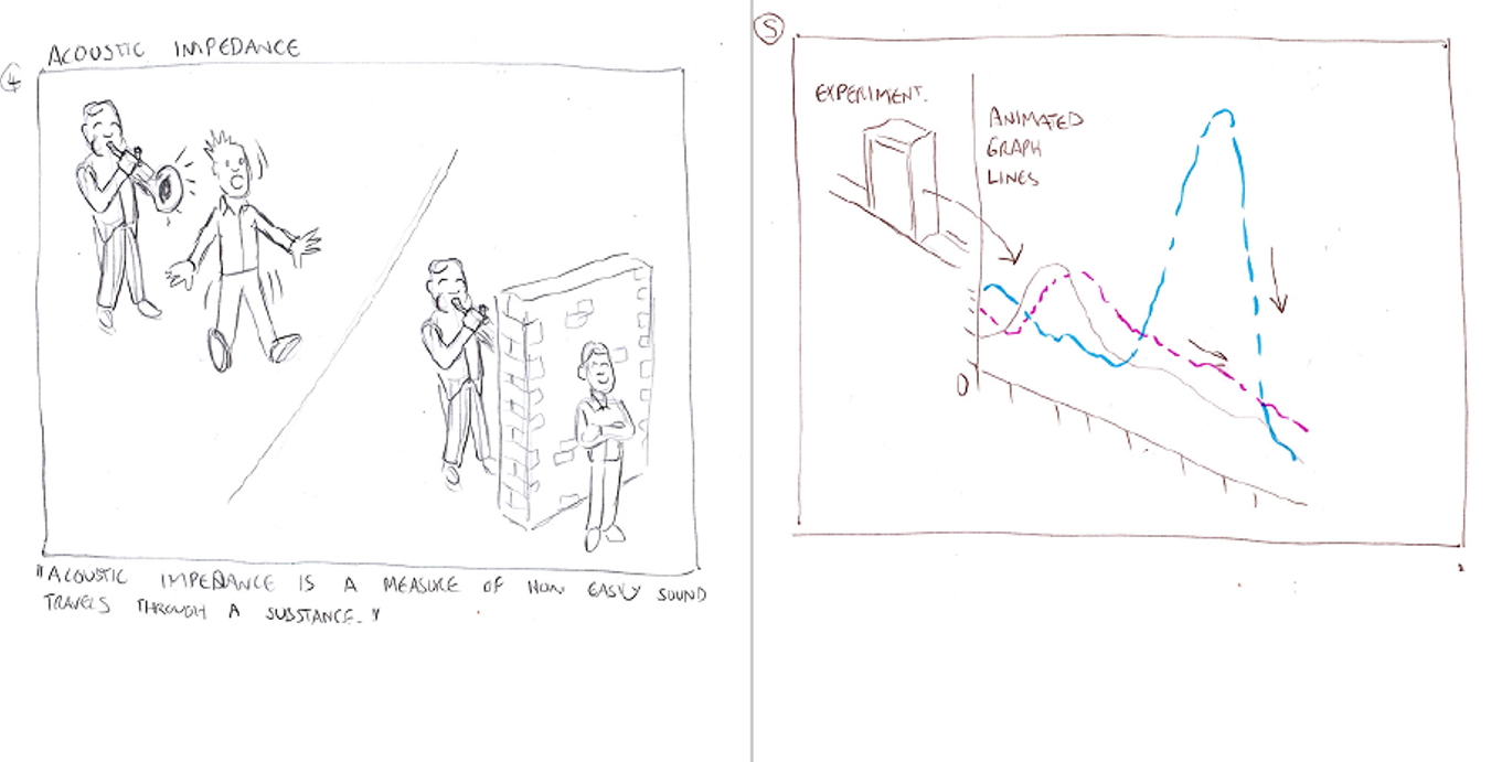
Sketches from the initial storyboard proposal. Credit: John Cooper, reproduced with kind permission from the artist
This project was completed during lockdown, so all our discussions were carried out over email or video conferencing.  Keeping the length of the script to a minimum was challenging, but after several iterations we arrived at the final version, which John narrates.

Here’s what John had to say, ‘I really enjoyed this project. The work the department does is fascinating, and it was an exciting challenge in generating visuals to complement their work on noise reduction.  It's good to learn new things while being creative.’
​
Here’s the finished product.  Watch out for those geese!
0 Comments

3-Minute Papers: Lightweight, Damage Resistant Materials

4/24/2020

0 Comments

 
We have prepared and tested a series of polymer-filled syntactic foams.  Foams with a high proportion of polymer microspheres showed excellent recovery and damage resistance in compression tests.

The first syntactic foam was developed in 1955 by the Bakelite Company of New York, and hailed as “A plastic foam, which promises to cut the partial cost of boat and airplane construction as much as 50%” [1].  It offered strength, insulation and tuneable properties in a lightweight material.

Syntactic foams are materials made up of hollow microspheres (commonly of glass, ceramic or plastic) held in a polymer matrix.  The strength and buoyancy of syntactic foams has led to their widespread use in marine applications, their sound absorbing properties find uses in acoustic applications, and they have even been used in World Cup footballs due to their low density and elastic recovery [2,3]. 
Picture
Syntactic foam sphere used as a subsurface float in oceanographic mooring. Photograph by Z22, distrubuted under a Creative Commons Attribution-Share Alike 4.0 International license
Picture
Adidas Fevernova 2002 World Cup Football containing a syntactic foam layer. Photograph by Warrenski, distributed under a Creative Commons Attribution-Share Alike 2.0 Generic license
Glass vs plastic

The mechanical behaviour of materials can be defined in terms of stress (the force applied to the material per unit area) and strain (the deformation in the material in response to stress).

Viscoelastic materials combine the behaviours of viscous fluids and elastic solids when deformed. A plot of stress vs strain shows hysteresis, where the unloading (reverse) curve follows a different path to the loading (forward) curve, because some energy is lost to the system as heat:
Picture
Stress (σ) vs strain (ε) for an elastic (a) and a viscoelastic (b) material. The red shaded hysteresis loop shows the energy dissipated as heat in the viscoelastic case. Image credit: Gene Settoon This work has been released into the public domain by its author at English Wikipedia.
Under increasing compression, syntactic foams with glass or ceramic microspheres typically respond in three stages:
  1. Elastic behaviour.
  2. Crushing of the microspheres (a region of low stiffness).
  3. Densification: the cavities fill up with debris from the crushed microspheres.

Stages 2 and 3 correspond to catastrophic damage to the microspheres, so glass microspheres are inappropriate for applications where foams will be under high strain.

Where plastic microspheres are used, the response of the material to compression also has three stages, but with less definition in-between:
  1. A small region of elastic behaviour.
  2. Buckling of the microsphere walls (a low stiffness region).
  3. Densification: the microsphere walls begin to touch.

The mechanical properties of syntactic foams with glass microspheres are well documented, but less work exists on plastic microsphere syntactic foams.
Our study
​

In this study we manufactured and tested polyurethane (PU) syntactic foams containing two grades of polymer microsphere.  The foams contained a 2%, 10% or 40% volume of microspheres.
Picture
Scanning electron microscope images of syntactic foams with microsphere grades 551 and 920.
The syntactic foams were tested up to medium (25% and 50%) strain alongside unfilled polyurethane.  Samples were compressed and unloaded five times and the response measured.
The foams showed viscoelastic behaviour, with hysteresis in the stress-strain curves.  Samples with a low volume of microspheres showed similar behaviour to unfilled PU, but increased proportions of microspheres led to some different results.  The 10% and 40% samples exhibited stress softening, where a smaller force is needed to achieve the same deformation in successive loadings.  This may be due to the buckled microspheres not fully recovering between load cycles.

After 1 week, the samples were re-tested.  They showed the same behaviour and little or no change in thickness, indicating that they had fully recovered from the previous testing.
Picture
Schematic showing the pattern adopted for cyclic compression testing.
Testing up to high strain (70%) revealed interesting behaviour.  Unfilled PU and foams with low concentrations of microspheres were damaged, but samples with higher concentrations of microspheres showed damage resistance.   Foams with 10% microsphere content were damaged only in the last of the 5 load/unload cycles, and foams with 40% appeared intact after test.
Picture
Stress-strain curves for unfilled PU and syntactic foams tested up to 70% strain. Inset: Images of the foams after testing. Damage appears reduced in foams with increasing content of polymer microspheres.
​Microscopy reveals cracks in the polyurethane in the damaged samples.  The microspheres mitigate the damage by presenting a barrier to crack propagation.  This is the opposite result to the case with glass and ceramic microspheres, where foams with higher volume fractions are less resistant to damage, due to the brittle nature of the microspheres.
Picture
SEM images of unfilled PU and syntactic foams with 2%, 10% and 40% polymer microspheres, after testing to 70% strain. The damage is significantly reduced in syntactic foams containing higher proportions of microspheres.
These results indicate that polymer-filled syntactic foams containing higher volume fractions of microspheres can show good elastic recovery and significant damage resistance.  They may provide an excellent alternative to glass and ceramic containing syntactic foams for applications that require low density materials with high resistance to damage under strain.
 
Read the full article here: doi.org/10.1016/j.compositesb.2020.107764

[1] Plastic Foam Developed for Boats and Planes, The Science News-Letter, 1955, 67(14),  213
[2] N. Gupta, S.E. Zeltmann, V.C. Shunmugasamy, D. Pinisetty Applications of polymer matrix syntactic foams, JOM, 2014, 66(2), 245-254
[3] For explanation of the anatomy of the 2014 Adidas Brazuca World Cup football: www.livescience.com/46299-microscopic-analysis-brazuca-world-cup-ball.html
0 Comments

3-Minute Papers: A New Model for the Mechanical Behaviour of Tendons

4/8/2020

0 Comments

 
We have developed a new model for the complex viscoelastic behaviour of tendons, which fits experimental data, and allows the behaviour of tendons under stress to be predicted accurately.

The USA reports 33 million musculoskeletal injuries per year, of which about half involve damage to soft tissues including tendons and ligaments (1).  Tendon repair is often slow, and incomplete (2).   An understanding of the mechanical behaviour of tendons is essential to the development of effective surgical reconstruction and prosthetic tissues.

Tendons are made up of fascicles: bundles of collagen fibrils embedded in a matrix containing water,  proteins such as elastin, and other substances.  Fibrils are up to 60 times thinner than spider silk, and crimped (folded in a concertina fashion).  ​Tendons connect bone to muscle, while ligaments connect bone to bone.

Picture
Schematic drawing of a tendon, showing fascicles and fibrils.
Viscoelastic materials
Tendons exhibit non-linear viscoelastic behaviour.  Viscoelastic materials combine the behaviours of both viscous fluids and elastic solids when deformed. Their mechanical behaviour is described in terms of stress (the force applied to the material per unit area) and strain (the deformation in the material in response to stress).

In a viscoelastic material:
  • A plot of stress vs strain shows hysteresis, where the state of a system depends on its history: when stress or strain is increased and then decreased, the outward and return graphs follow different curves:
Picture
Stress (σ) vs strain (ε) for an elastic (a) and a viscoelastic (b) material. Image credit: Gene Settoon This work has been released into the public domain by its author at English Wikipedia.
  • Under a constant stress (graph a, below) the strain increases over time (the material will deform, graph b, below).  This is called creep.  When the stress is removed the material will slowly return to its original shape.
Picture
Image credit: Theodor Langhorne Franklin. Distributed under the Creative Commons CC0 1.0 Universal Public Domain Dedication
  • Under a constant strain (a, below) , the stress decreases over time (stress relaxation, graph b, below)
Picture
Image credit: Theodor Langhorne Franklin. Distributed under the Creative Commons CC0 1.0 Universal Public Domain Dedication
Non-linear viscoelastic behaviour occurs when the stress varies in a non-linear fashion with strain rate.
​Our m​odel
Our model builds on existing models of tendon behaviour to account for fibril creep.  We model the individual behaviour of the fibrils and matrix as linear viscoelastic, but because we allow for a distribution of different lengths of fibril in a fascicle, we can account for the non-linearity that arises in the large-scale behaviour.
 
Strain is a measure of the change in length of the fascicle compared to its undeformed length. We consider the fascicle to contain multiple crimped fibrils, each with a critical length, where it is fully straightened and becomes taut.  The fibrils only begin to take up strain when they are taut.  This is illustrated in the clip below: 
The red threads represent fibrils.  As we stretch the fascicle the fibrils begin to straighten. The shortest fibrils are the first to take up strain.  By the end of the clip the bottom fibril has reached its critical length and begins to take up strain.  Stiffness increases as the stretch in the fascicle increases, and more fibrils reach their critical strain length.
 
When the stress is released, the fibrils begin to slacken.  Because of the viscoelastic memory effect, the critical strain at which a fibril straightens will change with each sequential load.
 
We can illustrate the model in two tests: relaxation test and cycle test.
​Relaxation test
In the relaxation test the fascicle is rapidly stretched (strained), then held constant for a time, and this is repeated in a stepwise fashion, illustrated by the top graph (below, left).  The middle graph shows the corresponding strain in a fibril which reaches its critical length and begins to take up strain at time tA.  The bottom graph shows the fibril stress, and the relaxation effect is seen.
​Cycle test
In the cycle test the fascicle is gradually stretched then unloaded.  This is repeated twice (top graph, below, right).  The graphs below it show the associated strain (middle) and stress (bottom) in a fibril.
 
On first unloading, the stress relaxation and creep effects are seen. As a result of the first cycle, the critical strain length for the second loading is longer than the first for fibrils that have taken up strain in the first cycle. For fibrils that do not straighten fully in the first cycle, the critical length will be unchanged. 
Picture
Relaxation test
Picture
Cycle test
​Time-evolution
The overall response of the fascicle depends on the relative proportions of matrix and fibrils, and the distribution of fibril lengths.  Crucially, in our model, accounting for fibril creep allows us to predict how the fibril length distribution will evolve over time.  The animations below show how the length distribution changes during the cycle test.  The animation on the left does not account for fibril creep, while the one on the right does.  
​This element of our model allows a close fit to experimental data and provides a better understanding and more accurate prediction of tendon behaviour.
Read the full paper here: https://doi.org/10.1115/1.4045662

(1) F. Wu, M. Nerlich and D. Docheva, Tendon Injuries, Basic Science and New Repair Proposals, EFORT Open Reviews, 2017, 2, 332-342 10.1302/2058-5241.2.160075
​(2) R. James, G. Kesturu, G. Balian and A. Chhabra, Tendon: Biology, Biomechanics, Repair, Growth Factors, and Evolving Treatment Options, The Journal of Hand Surgery, 2008, 33, 102-112 doi.org/10.1016/j.jhsa.2007.09.007
0 Comments

3-Minute Papers: Slow Sound Paves the Way for Space-Saving Noise Cancellation Devices

3/30/2020

0 Comments

 
We have modelled, designed and printed a metamaterial with a structure that reduces the effective speed of sound in air by half, opening up the potential for space-saving noise cancellation devices.

Noise pollution can reduce our quality of life, and even our life expectancy.  A 2014 report from the European Environment Agency estimates that 10,000 premature deaths and 43,000 hospital admissions for coronary heart disease and stroke can be attributed to noise exposure in Europe each year. (1)  The urgent need for efficient noise cancellation devices is clear.

Destructive Interference

Noise cancellation devices often work on the principle of destructive interference, where sound waves are combined so that they cancel each other out.
​
Here’s how it works:
 
One tool that may be employed to reduce noise from engines, fans and other devices is a Quarter Wavelength Resonator (QWR).  This is a side branch in a duct that redirects sound waves so that they interfere destructively.  The length of the QWR is ¼ of the wavelength of the noise frequency to be attenuated. 

​The animation below shows how a QWR functions:
Part of the sound wave is diverted into the QWR, reflects off the end wall and then recombines with the undiverted wave.  The diverted wave has travelled an additional ½ wavelength, so the waves now re-combine destructively, cancelling the noise. 
​
There are limitations to this approach: the size of the resonator depends on the wavelength of the noise we want to reduce.  Low frequency noises have long wavelengths, so the size of the resonator required soon becomes impractically large.

Acoustic Metamaterials

We used a mathematical mapping process called Transformation Acoustics to design and 3D print a metamaterial that has the potential to overcome the size limitations of QWRs for reducing low frequency noise.

Metamaterials are special materials with properties that are not found in conventional materials.  Unlike conventional materials, the properties of metamaterials are defined by their structures rather than by their chemical make-up.  Acoustic metamaterials have geometries that allow the manipulation of sound waves in ways not previously achievable.

Our metamaterial has arrays of elliptical cylinders which stretch the apparent space inside the resonator, with the result that the effective speed of sound is reduced by half.  Crucially, it does this while maintaining a close match to the impedance of sound in air across a range of frequencies. 
Acoustic impedance is a measure of how easily sound travels through a substance.  When sound passes between media with very different impedance, some of the sound is reflected and not transmitted.  For the destructive interference from the QWR to work effectively, transmission of sound energy into the side branch must be efficient, so a close match to the impedance of air is required.
Picture
Experimental results illustrating the sound reduction from three resonators of equal length. Branch (a), dotted red curve, has a metamaterial structure of ellipses centred on the branch centre. Branch (b), solid green curve, has a metamaterial structure of ellipses centred on the branch walls. Branch (c), dashed blue curve, is a standard air filled resonator for comparison. The halving of the frequency of noise reduction in the metamaterial is clearly visible.

Space-Saving Devices

Slowing down the sound by half has the effect of halving the frequency of the noise that can be cancelled with the same size of resonator, or halving the size of the resonator that operates on a particular frequency, because of the relationship:  speed of sound = wavelength x frequency

When the speed of sound is halved, either the length of the resonator, or the frequency of the sound it reduces must also be halved.  This allows significant space savings and opens up the possibility of building more practical, size efficient devices for the reduction of low frequency noise.

Read the full paper here: doi.org/10.1063/1.5022197

(1) European Environment Agency Report No. 10/2014: www.eea.europa.eu/publications/noise-in-europe-2014
0 Comments

A Fruitful Visit to Australia

3/20/2020

0 Comments


Erik Garcia Neefjes

3rd Year PhD Student

​One of the most rewarding experiences of my PhD is being able to attend to conferences and the opportunity to introduce myself and present my research to a wide audience of professionals. After two and a half years of PhD studies, I have had the chance to visit some great places within the UK and Europe, and now Australia! KOZWaves is a biennial conference focused on the study wave science and is always held somewhere within Australia and New Zealand. I first heard of it in my PhD first year and thought how amazing it would be to get to know a new community and give a talk at this event. Two years later I was very happy to receive the news that my talk: "Wave Propagation in Thermo-Visco-Elastic Continua" had been accepted to KOZWaves 2020 which was held at the University of Melbourne from the 17-19th of February.
 
The conference exceeded my expectations with great speakers talking from gravitational waves to water waves as well as light, sound and vibrations (to name just a few!) They showcased - the well known fact of - how waves describe so many physical phenomena of the world that surrounds us.
Picture
Picture
​The next step of the journey was a visit to the University of Adelaide in South Australia which is an 80 minute flight from Melbourne's Tullamarine Airport. As a keen surfer myself, before taking the flight I paid a visit to URBNSURF, a new facility for surfing artificial waves (again waves!) in a big pool right by the airport which was super fun!
Picture
Picture
I spent three fantastic days at the University of Adelaide visiting Dr. Luke Bennetts. I gave a talk to the Mechanics group on "Modelling Thermo-Viscous Damping in Continua". 
Picture
Picture

​We also discussed some interesting problems involving the interaction of waves in ice-ocean systems together with Prof. Malte Peter, who was also visiting Luke. They showed me around Adelaide where the Fringe festival was, coincidentally, also taking place. Thanks again Luke and Malte!

​After this, I headed up to Sydney and visited Prof. Nicole Kessissoglou and her research group at the University of New South Wales with whom I spent a great day and was shown some of their fantastic work in the field of acoustic metamaterials. I went for a small trip down to the stunning South Coast and got to see first hand the impact that the fires had on the small communities, it was devastating to see how so many homes have been completely burned down as well hectares of land.
Picture
Picture
Finally, I visited Dr. Stuart Hawkins at Macquarie University in Sydney and some of his colleagues including Dr. Elena Vynogradova and her PhD student Martin Sagradian. I gave an hour long talk similar to the one I presented in Adelaide and had some interesting conversations. Stuart showed me some very impressive numerical computations via the use of the T-matrix approach for multiple scattering problems.
I would like to thank the MWM group and my supervisors for giving me this opportunity and look forward to the next few months.
0 Comments
<<Previous
Forward>>

    About us

    The Mathematics of Waves and Materials group are are a research group in the Department of Mathematics at the University of Manchester.  We work on the theoretical, numerical and experimental aspects of both materials and waves. See our research page for more information and details.

    Archives

    January 2022
    December 2021
    September 2021
    February 2021
    November 2020
    October 2020
    August 2020
    June 2020
    May 2020
    April 2020
    March 2020
    January 2020

    Categories

    All
    3 Minute Papers
    History Of Science
    Key Concepts
    Materials
    Metamaterials
    My PhD In 5 Pictures
    News
    People
    Research
    Women In Mathematics

    RSS Feed

Proudly powered by Weebly